Water face thin oil film recycling and separating device

A technology of separation device and thin oil film, which is applied in the direction of separation method, liquid separation, grease/oily substance/floating matter removal device, etc., which can solve the problems of small oil sweeping surface, poor effect and low efficiency

Active Publication Date: 2014-09-17
中国船舶重工集团公司第七〇二研究所
View PDF7 Cites 7 Cited by
  • Summary
  • Abstract
  • Description
  • Claims
  • Application Information

AI Technical Summary

Problems solved by technology

Chinese patent CN00256382.7 discloses an oil slick recovery ship, which includes a hull and an oil skimmer, wherein the front deck of the hull has a groove, the front end of the groove is open, and the oil skimmer is installed in the groove , a diversion pump is installed on the inner side of the lower end of the oil skimmer. When recovering the oil spill, turn on the diversion pump, and the water surface will counteract the effect of the bow wave, and quickly lead the spilled oil to the oil recovery zone, which is in the shape of a grid Oil filter and oil recovery belt, water can leak from the grid, and oil adheres to the oil recovery belt, which greatly improves the recovery rate of oil spilled, but because the oil recovery belt is used to collect oil, there is a requirement for the viscosity of the slick oil, for those For relatively thin oil slicks, the effect of oil collection with oil collection belt is not good, and the oil sweeping surface is small
For other types of oil collection equipment in the prior art, such as rotary table oil collection equipment, because it relies on the surface of the disk to collect oil, it is only suitable for recovering medium and high viscosity oil spills. , the water content is relatively large, and oil-water separation equipment is required for secondary treatment, and the efficiency is low

Method used


Image

  • Water face thin oil film recycling and separating device
  • Water face thin oil film recycling and separating device
  • Water face thin oil film recycling and separating device

Examples


Embodiment Construction

[0020] The specific implementation manner of the present invention will be described below in conjunction with the accompanying drawings.

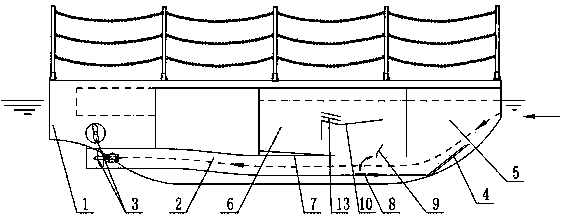
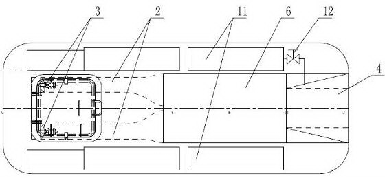
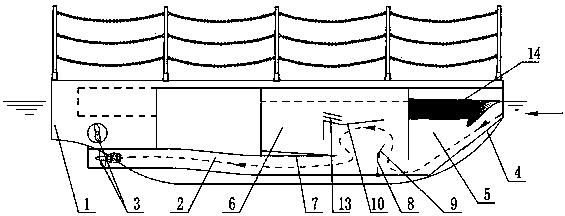
[0021] See figure 1 , figure 2 , the present invention comprises a hull 1, the hull 1 is provided with a main channel 2 for the entry and passage of oily water, the main channel 2 extends from the bow of the hull 1 to the stern, the entrance of the main channel 2 is located at the bow of the hull 1, the main channel The outlet of channel 2 is located at the stern of hull 1, the entrance of main channel 2 is higher than the outlet of main channel 2, and the stern of hull 1 is provided with propulsion device 3; An adjustment cofferdam 4 is arranged on it, which is used to adjust the entrance of the main channel 2 according to the incoming flow velocity, thereby adjusting the flow velocity at the entrance of the main channel 2. The flow velocity at the entrance can be calculated according to the flow rate of the main channel 2, specifically...


PUM


Abstract

The invention discloses a water face thin oil film recycling and separating device. The device comprises a boat body, wherein the boat body is provided with a main runner enabling oily water to enter and pass; a propelling device is arranged on a stern; an adjustment cofferdam is arranged on the front section, which is inclined like a minus grade, of the main runner; two adjacent separation cabins are arranged on the boat body; the front end of the primary separation cabin is communicated with the external oily water by the inlet of the main runner; a discharge hole at the rear end of the cabin is communicated with the main runner; guide plates are respectively arranged on the bottom of the secondary separation cabin and inside the secondary separation cabin; the two guide plates are used for forming an inertia cabin used for secondary oil and water separation in the rear of the secondary separation cabin; a rotating flashboard and a guide plate are arranged on the rear end of the discharge hole of the primary separation cabin; the rotating flashboard can obstruct or open the main runner, and can form a transition runner of the oily water when the main runner is obstructed, together with the guide plate at the rear end of the discharge hole of the primary separation cabin and the guide plates on the secondary separation cabin; the two separation cabins are connected with a recovery cabin by suction pipelines; oil level sensors are arranged on the separation cabins. The water face thin oil film recycling and separating device is used for effectively recycling and separating large-area or local regional thin oil film on the water face.

Description

technical field [0001] The invention relates to the technical field of oil spill recovery and treatment in water areas, in particular to a device for recovering and separating thin oil films on or near the water surface. Background technique [0002] In the surface oil spill emergency treatment technology, the oil slick recovery ship is the most important equipment in this field. Chinese patent CN00256382.7 discloses an oil slick recovery ship, which includes a hull and an oil skimmer, wherein the front deck of the hull has a groove, the front end of the groove is open, and the oil skimmer is installed in the groove , a diversion pump is installed on the inner side of the lower end of the oil skimmer. When recovering the oil spill, turn on the diversion pump, and the water surface will counteract the effect of the bow wave, and quickly lead the spilled oil to the oil recovery zone, which is in the shape of a grid Oil filter and oil recovery belt, water can leak from the gri...

Claims


Application Information

Patent Timeline
Patent Type & Authority Applications(China)
IPC IPC(8): E02B15/10C02F1/40
CPCY02A20/204
Inventor 宋长友姚木林李明政吴宝山倪阳郑文涛张静安伟
Owner 中国船舶重工集团公司第七〇二研究所
Why Eureka
Try Eureka