Electric motor direct-drive dead-weight balanced type beam-pumping unit
A motor, balanced technology, applied in wellbore/well components, production fluids, earthwork drilling and other directions, can solve the problems of poor work stability, high maintenance costs, complex structures, etc., to achieve stable work performance, reduce maintenance costs, The effect of simplifying the transmission mechanism
- Summary
- Abstract
- Description
- Claims
- Application Information
AI Technical Summary
Problems solved by technology
Method used
Image

Examples
Embodiment Construction
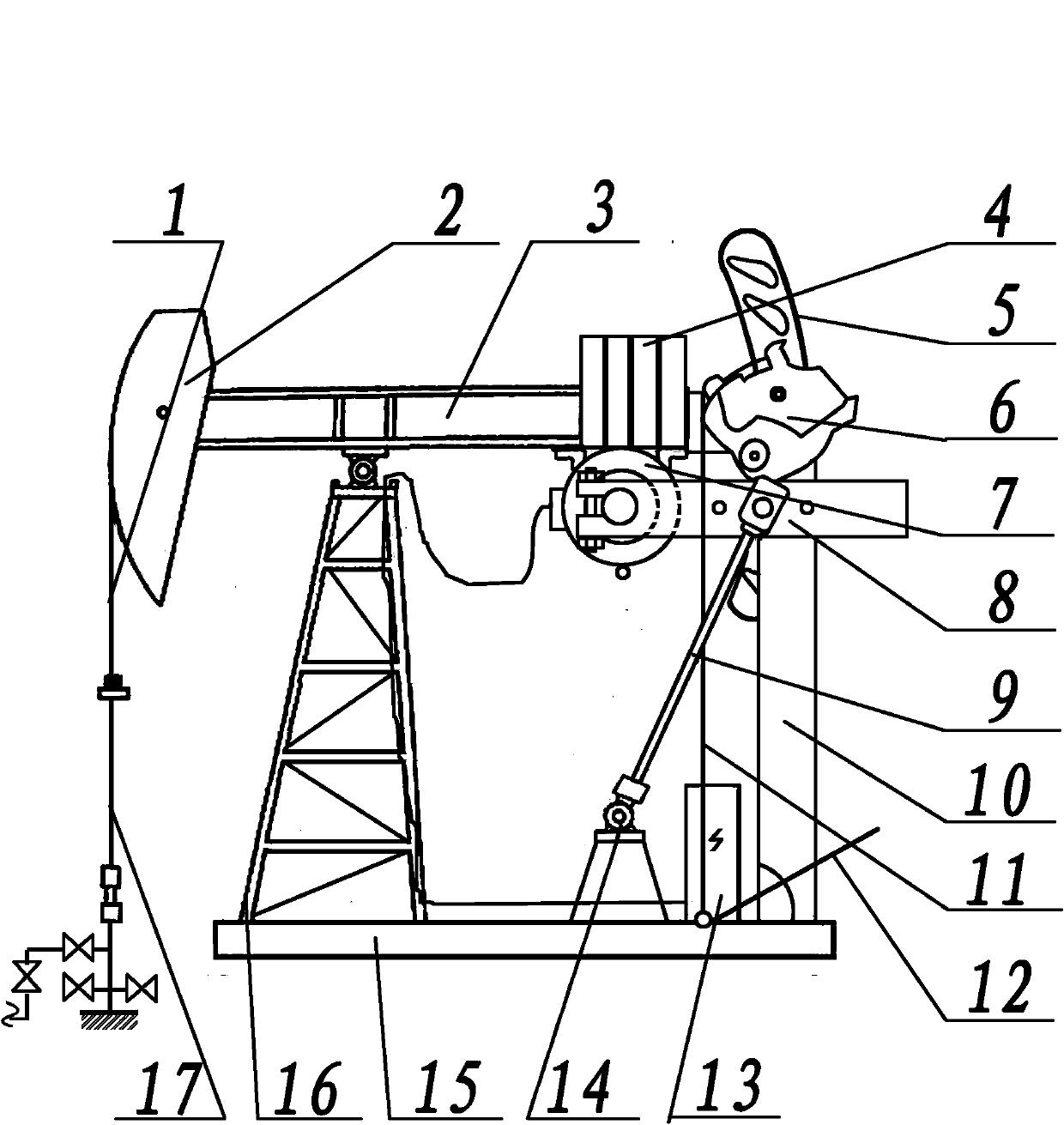
[0014] Motor direct drive self-weight balanced beam pumping unit consists of rope suspension 1, donkey head 2, beam 3, balance weight 4, brake disc 5, brake device 6, motor 7, crank 8, connecting rod 9, rear bracket 10. Brake connecting rod 11, brake handle 12, distribution box 13, hinge 14, base 15, and front bracket 16. The rope hanger 1 of the motor direct-driven self-weight balanced beam pumping unit is suspended on the donkey head 2, the front end of the beam 3 is connected with the donkey head 2, the front end of the base 15 is provided with a front bracket 16, and the front bracket 16 is connected to the donkey head 2. The middle part of the beam 3 is connected by the middle bearing, the rear bottom surface of the beam 3 is provided with a motor 7, and the motor 7 shaft is equipped with a crank 8, the crank 8 is connected with the connecting rod 9 through the crank pin assembly, and the other end of the connecting rod 9 is connected with the fixed The hinge 14 on the ...
PUM
 Abstract
Description
Claims
Application Information
 - R&D
- Intellectual Property
- Life Sciences
- Materials
- Tech Scout
- Unparalleled Data Quality
- Higher Quality Content
- 60% Fewer Hallucinations
Browse by: Latest US Patents, China's latest patents, Technical Efficacy Thesaurus, Application Domain, Technology Topic, Popular Technical Reports.
© 2025 PatSnap. All rights reserved.Legal|Privacy policy|Modern Slavery Act Transparency Statement|Sitemap|About US| Contact US: help@patsnap.com