Electronic pole changing-based induction motor control system and control method thereof

a control system and induction motor technology, applied in the field of induction motors, can solve the problems of difficult control, inability to meet the requirement of large torque at low speed, and difficulty in controlling, so as to increase the low-speed torque enhance the control accuracy and operation efficiency of the induction motor control system, and widen the speed governing operation range

Active Publication Date: 2020-02-27
SHENZHEN YUNLIN ELECTRIC CO LTD
View PDF3 Cites 3 Cited by
  • Summary
  • Abstract
  • Description
  • Claims
  • Application Information

AI Technical Summary

Benefits of technology

[0019](1) Speed governing of the induction motor control system is achieved by using pole-changing, without the need of cutting the power off, or altering the wiring either during the pole-changing control process, effectively enhancing the control accuracy and operation efficiency of the induction motor control system.
[0020](2) The control unit controls a plurality of inversion driving units to alter the current direction or phase angle of a plurality of three-phase windings, making the induction motor

Problems solved by technology

However, when the synchronous rotational speed of motor is higher than the synchronous rotational speed which corresponds to the pole-pair number at the fundamental frequency, the torque provided by the motor decreases non-linearly, and it leads to difficult control when the synchronous rotational speed of motor increases to a certain extent.
Conventional frequency control fails to meet the requirement of providing large torque at low

Method used


Image

  • Electronic pole changing-based induction motor control system and control method thereof
  • Electronic pole changing-based induction motor control system and control method thereof
  • Electronic pole changing-based induction motor control system and control method thereof

Examples


embodiment 1

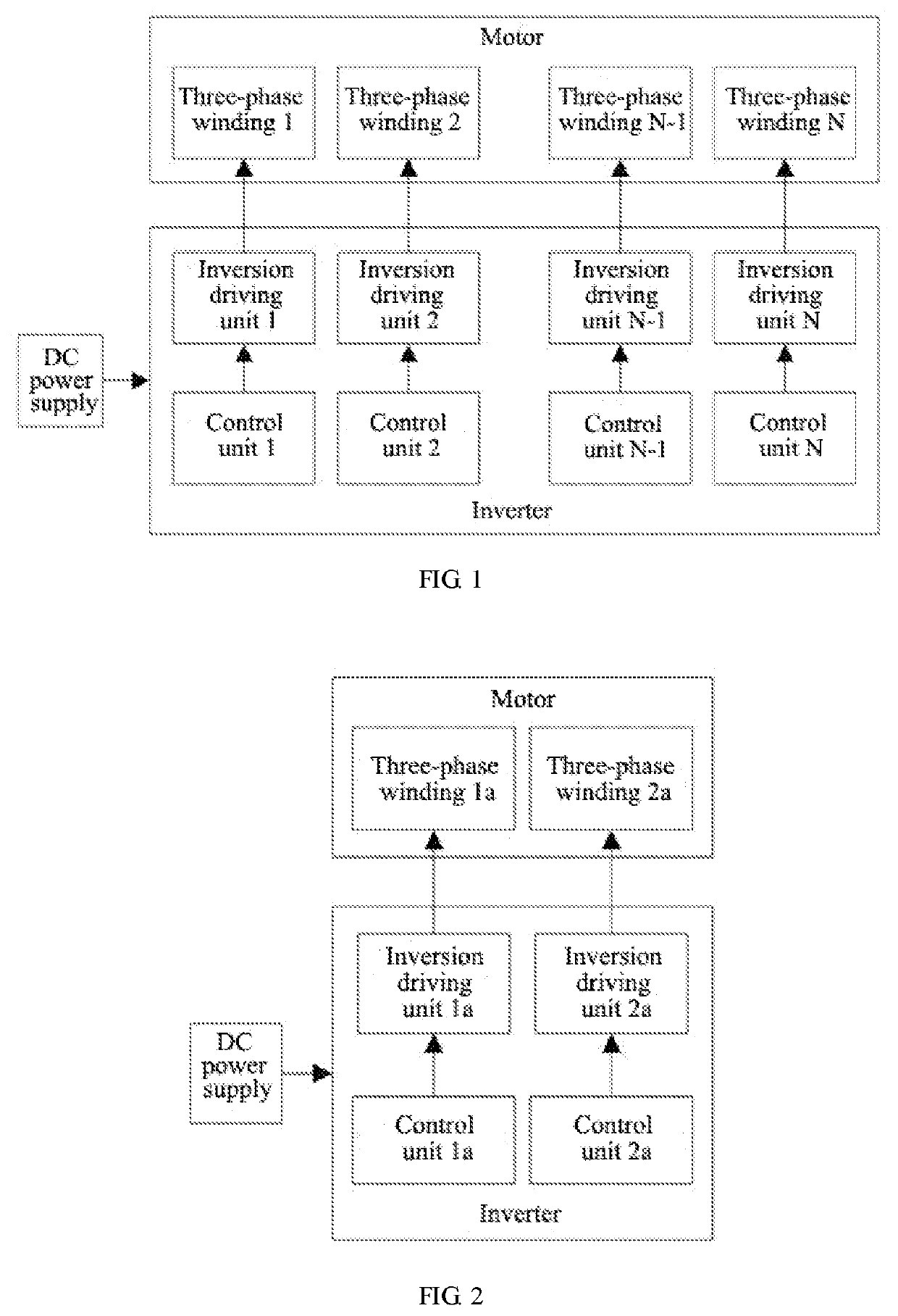
[0032]As shown in FIG. 1, an electronic pole changing-based induction motor control system comprises a motor, an inverter and a DC power supply. The inverter is connected with the motor and the DC power supply respectively for converting a direct current supplied by the DC power supply into an alternating current supplied to the motor.

[0033]The motor comprises N three-phase windings, wherein N is an integer bigger than 1. Said N three-phase windings are the three-phase winding 1, the three-phase winding 2 . . . and the three-phase winding N, respectively. The inverter comprises N inversion driving units and at least one control unit. Said N inversion driving units are the inversion driving unit 1, the inversion driving unit 2 . . . and the inversion driving unit N, respectively. Each inversion driving unit is connected with one three-phase winding, that is to say, the inversion driving unit n is connected with the three-phase winding n (n is an arbitrary integer from 1 to N). The co...

embodiment 2

[0039]As shown in FIG. 2, an electronic pole changing-based induction motor control system of the present embodiment comprises a motor, an inverter and a DC power supply. The motor comprises two three-phase windings, i.e. three-phase winding 1a and three-phase winding 2a, respectively. The inverter comprises two inversion driving units and two control units. Said two inversion driving units are inversion driving unit 1a and inversion driving unit 2a, respectively. Said two control units are control unit 1a and control unit 2a, respectively. The control unit 1a controls the inversion driving unit 1a to alter a current direction or a phase angle of the three-phase winding 1a. The control unit 2a controls the inversion driving unit 2a to alter a current direction or a phase angle of the three-phase winding 2a.

embodiment 3

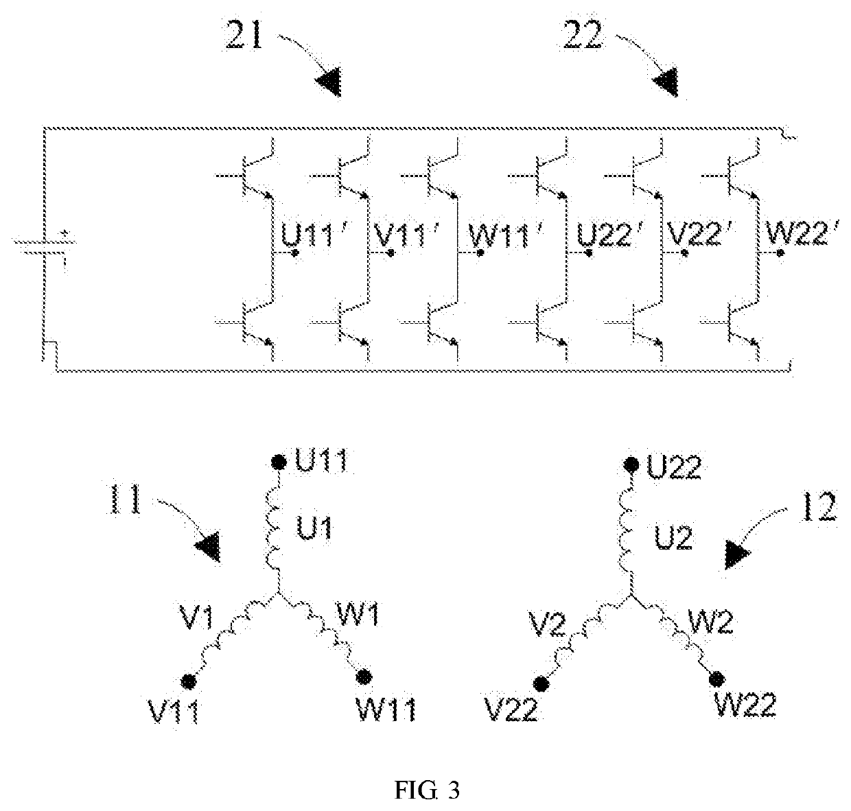
[0040]As shown in FIG. 3, the induction motor control system of the present embodiment employs a YY AC-motor. FIG. 3 only shows a partial circuit diagram for achieving pole changing. In the present embodiment, the motor comprises two three-phase windings, i.e. three-phase winding 1b (11) and three-phase winding 2b (12), respectively. These two three-phase windings form a 2Y structure. The inverter comprises two inversion driving units, i.e. inversion driving unit 1b (21) and inversion driving unit 2b (22), respectively. The control unit (not shown) controls the inversion driving unit 1b (21) to alter a current direction or a phase angle of the three-phase winding 1b (11), and controls the inversion driving unit 2b (22) to alter a current direction or a phase angle of the three-phase winding 2b (12). Particularly, the number of the control unit can be one or two.

[0041]The inversion driving unit comprises three output ends. Each three-phase winding comprises three sub-windings, and in...


PUM


Abstract

The present invention relates to an electronic pole changing-based induction motor control system and a control method thereof. Such induction motor control system comprises an induction motor, an inverter and a DC power supply. The inverter is connected with the motor and the DC power supply respectively, for converting a direct current supplied by the DC power supply to an alternating current supplied to the motor. The motor comprises N three-phase windings (11, 12; 31, 32). The inverter comprises N inversion driving units (21, 22; 41, 42) and at least one control unit. Each inversion driving unit is connected with one three-phase winding. The control unit controls the inversion driving unit to generate a current of the three-phase winding connected thereto, and frequency, amplitude and phase of the current can be controlled by the control unit. The control unit alters current directions or phase angles of at least part of the three-phase windings according to a synchronous rotational speed of the motor, making N three-phase windings form at least two pole-pair numbers. The induction motor control system enhances the low-speed torque and broadens the speed governing operation range, thereby enhancing the control accuracy and operation efficiency, and simplifying a peripheral transmission mechanism.

Description

TECHNICAL FIELD[0001]The present invention relates to the field of induction motors, and particularly relates to an electronic pole changing-based induction motor control system and a control method thereof.BACKGROUND[0002]At present, induction motor control systems are applied in fields such as electric vehicle, elevator, machine tool servo system and the like increasingly. Generally, these application fields require the induction motor control system to provide a large torque at low speed, while require the induction motor control system to possess a wide speed governing operation range.[0003]Generally, under the circumstance of a constant pole-pair number, as a synchronous rotational speed of motor increases, the motor provides a constant torque when the synchronous rotational speed of motor is less than a synchronous rotational speed which corresponds to the pole-pair number at the fundamental frequency. However, when the synchronous rotational speed of motor is higher than the ...

Claims


Application Information

Patent Timeline
IPC IPC(8): H02P25/20
CPCH02P25/20
Inventor ZHANG, JING
Owner SHENZHEN YUNLIN ELECTRIC CO LTD
Why Eureka
Try Eureka