Wear-resistance high-pressure single-screw pump

A single-screw pump and screw technology, applied to pumps, pump components, rotary piston pumps, etc., can solve problems such as degraded pump conditions, increased bushing wear, and poor rotor fit

Inactive Publication Date: 2014-09-17
无锡市恒烽水煤浆有限公司 +1
View PDF9 Cites 12 Cited by
  • Summary
  • Abstract
  • Description
  • Claims
  • Application Information

AI Technical Summary

Problems solved by technology

But this improvement brings another disadvantage. The shape of the rubber bushing may not fit the rotor well before and

Method used


Image

  • Wear-resistance high-pressure single-screw pump
  • Wear-resistance high-pressure single-screw pump
  • Wear-resistance high-pressure single-screw pump

Examples


Embodiment 1

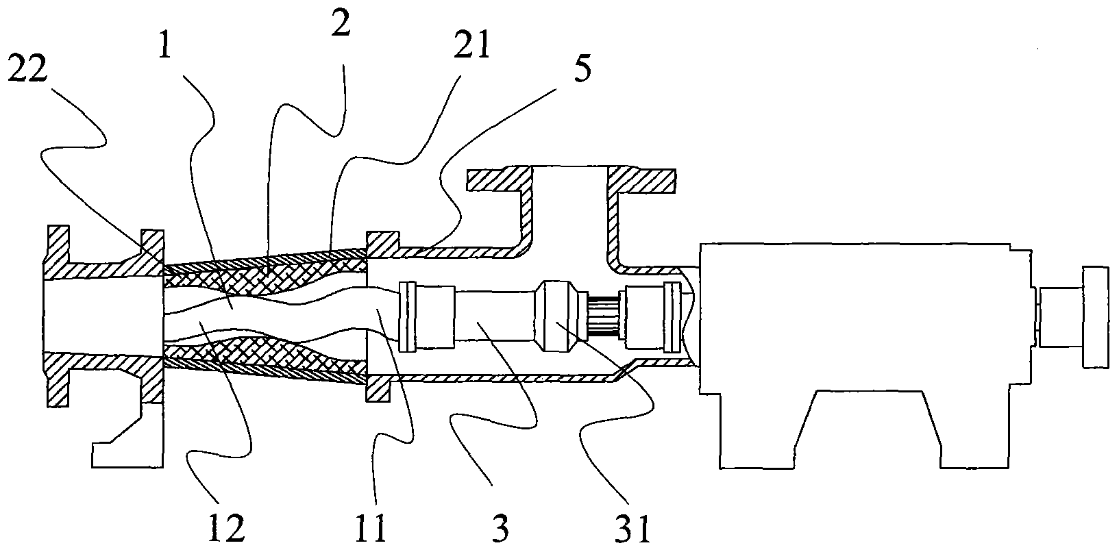
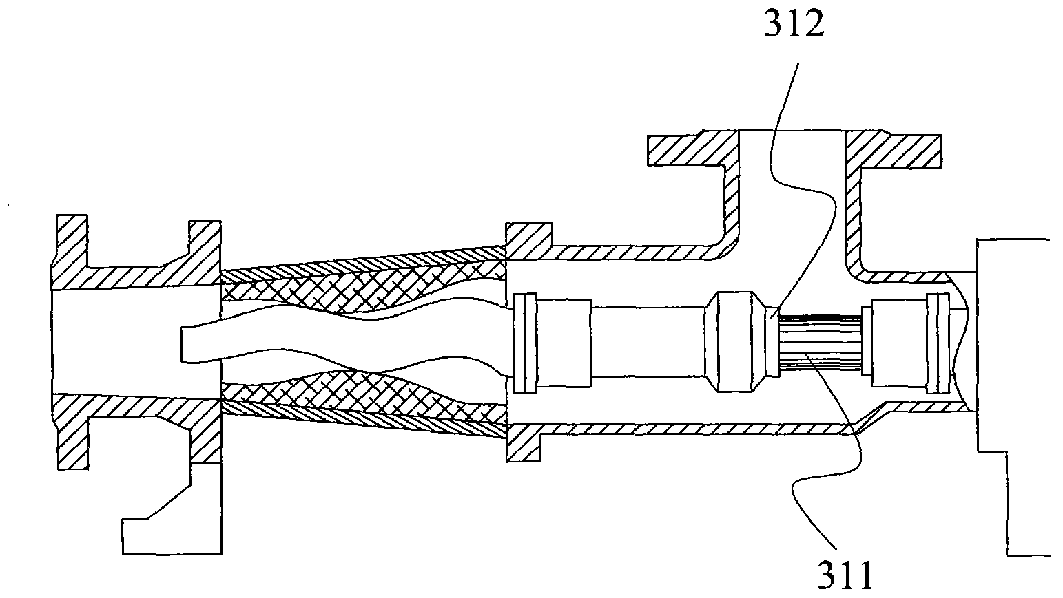
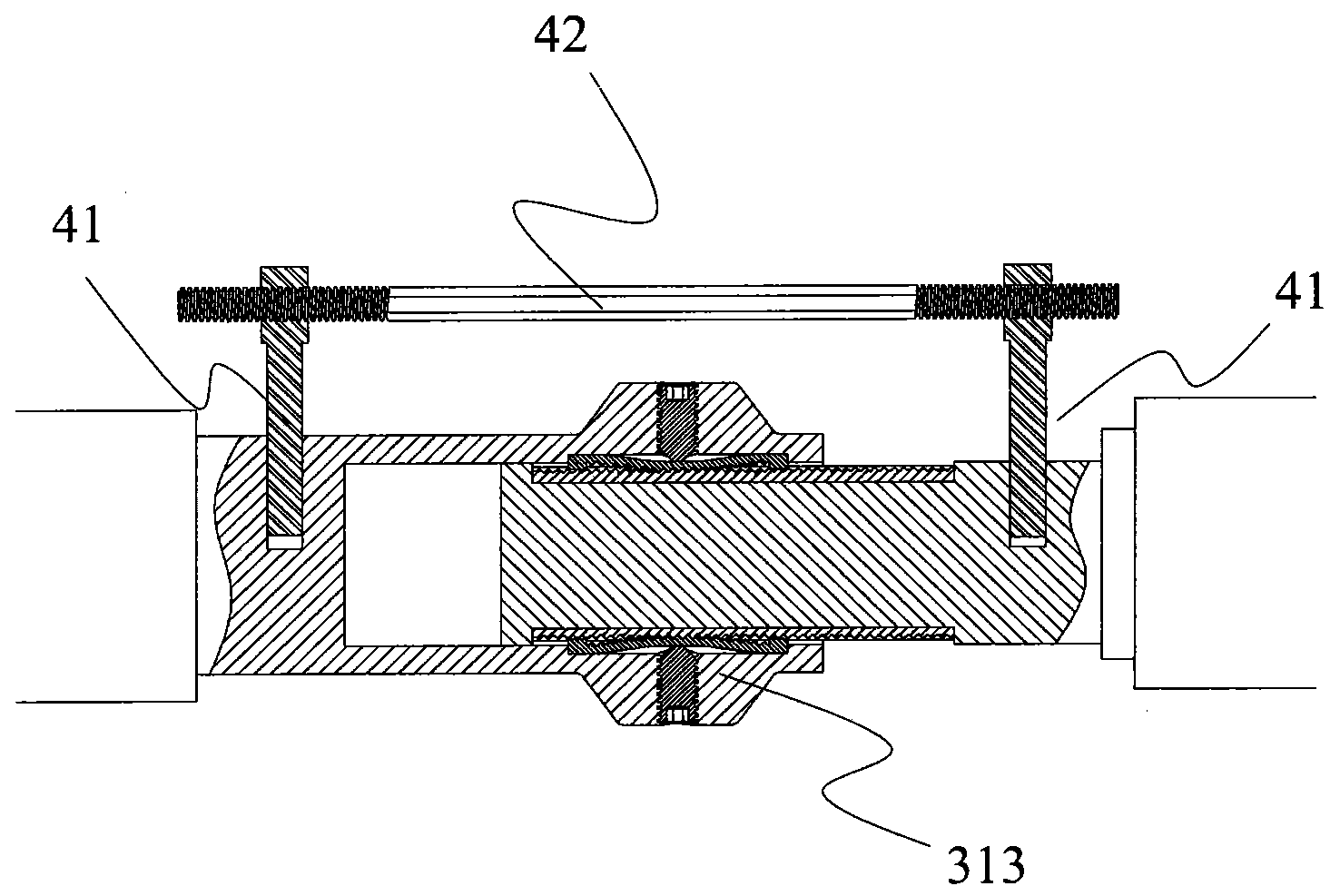
[0025] See attached Figure 1-6 . A single-screw pump comprises a rotor 1 in the shape of a single-head helical screw, a stator 2 with a double-head helical cavity bushing, a connecting shaft 3 with a universal joint, and a feed chamber 5 . One end of the rotor connected to the connecting shaft is the feed end 11 , and the other end is the discharge end 12 . The stator is also divided into corresponding feed end 21 and discharge end 22 . The single-headed helical screw and the double-ended helical cavity are arranged in the shape of a trumpet with a thick feed end and a thin discharge end, and the length of the feed end of the screw is somewhat redundant. The screw bushing position adjusting device is a length adjusting device 31 arranged on the connecting shaft. The length adjusting device 31 includes a spline 311 , a sleeve 312 and a length locking device 313 .

[0026] Locking device 313 see attached Figure 3-4 , consisting of two sets of top screws 3131, spring teeth...

Embodiment 2

[0029] See attached Figure 7-8 , a single-screw pump, including a rotor 1 in the shape of a single-head helical screw, a stator 2 with a double-head helical cavity bushing, a connecting shaft 3 with a universal joint, and a feed chamber 5 . One end of the rotor connected to the connecting shaft is the feed end 11 , and the other end is the discharge end 12 . The stator is also divided into corresponding feed end 21 and discharge end 22 . The single-headed helical screw and the double-ended helical cavity are set in the shape of a trumpet with a thick feed end and a thin discharge end, and the length of the discharge end of the screw is somewhat redundant. The position adjusting device of the screw bush is a telescopic joint 51 arranged on the feed chamber 5 .

[0030] When the new pump has just been assembled, the expansion joint is in the longest state, and the discharge end of the screw is flush with the discharge end of the bushing. After a period of use, the bushing and...


PUM


Abstract

The invention relates to a wear-resistance high-pressure single-screw pump. An existing single-screw pump has the problems that the rotor interference is reduced, the pressure bearing capacity of the pump is lowered and the leakage amount is increased because a stator rubber bush is easy to wear during usage. The invention discloses an improved scheme, in which a screw and a bush cavity of the single-screw pump are remodel to a cone like shape with a wide feed end and a thin discharge end, and a position adjusting device is arranged on a connecting part between the screw and a bush; when the screw and the bush are worn, the screw moves towards the discharge end so as to increase the interference among the rotors, namely compensate the wear; the screw and the bush are meshed with each other to form a sealed cavity the volume of which is gradually reduced during transverse motion, so that the pressure is increased; the length of the screw bush is lengthened by multiple times of the screw pitch and the wear is equivalent to connecting multiple screws in series, and thus the maximum pumping pressure can be greatly increased.

Description

technical field [0001] The invention relates to a screw pump. Background technique [0002] The single screw pump belongs to the rotor type volumetric pump, which relies on the meshing of the screw and the bush to produce volume changes in the suction chamber and the discharge chamber to transport the liquid. It is an internal meshing hermetic screw pump, the main working parts are composed of a bush with a double-ended helical cavity and a single-ended helical screw engaged with it in the stator cavity. Generally, the bushing with a double-ended helical cavity and the supporting cylinder outside it are called a stator, and the single-ended helical screw is called a rotor. When the rotor is driven to make a planetary rotation around the center of the stator through the universal joint connection shaft, the stator-rotor pair is continuously meshed to form a sealed cavity. Auxiliary delivery to the extrusion end. [0003] The advantages of this type of pump are strong adapt...

Claims


Application Information

Patent Timeline
IPC IPC(8): F04C2/107F04C15/00F04C15/06
Inventor 张传忠刘峰
Owner 无锡市恒烽水煤浆有限公司
Why Eureka
Try Eureka