Dynamic gear clearance eliminating device

A dynamic and anti-backlash technology, applied in hoisting devices, portable lifting devices, belts/chains/gears, etc., can solve the problems of inability to ensure the synchronization of helical gears, complex structural design, etc., to reduce impulse and Vibration, simple structure design, cost reduction effect

Inactive Publication Date: 2014-09-17
CHANGCHUN INST OF OPTICS FINE MECHANICS & PHYSICS CHINESE ACAD OF SCI
View PDF4 Cites 3 Cited by
  • Summary
  • Abstract
  • Description
  • Claims
  • Application Information

AI Technical Summary

Problems solved by technology

[0005] The purpose of the present invention is to provide a dynamic anti-backlash device for gears in order to solve the problem that the existing gear anti-backlash structure cannot well ensure the synchronization of the rotation of the upper and lower parts of the helical gear, and the structural design is relatively complicated.

Method used


Image

  • Dynamic gear clearance eliminating device

Examples


Embodiment Construction

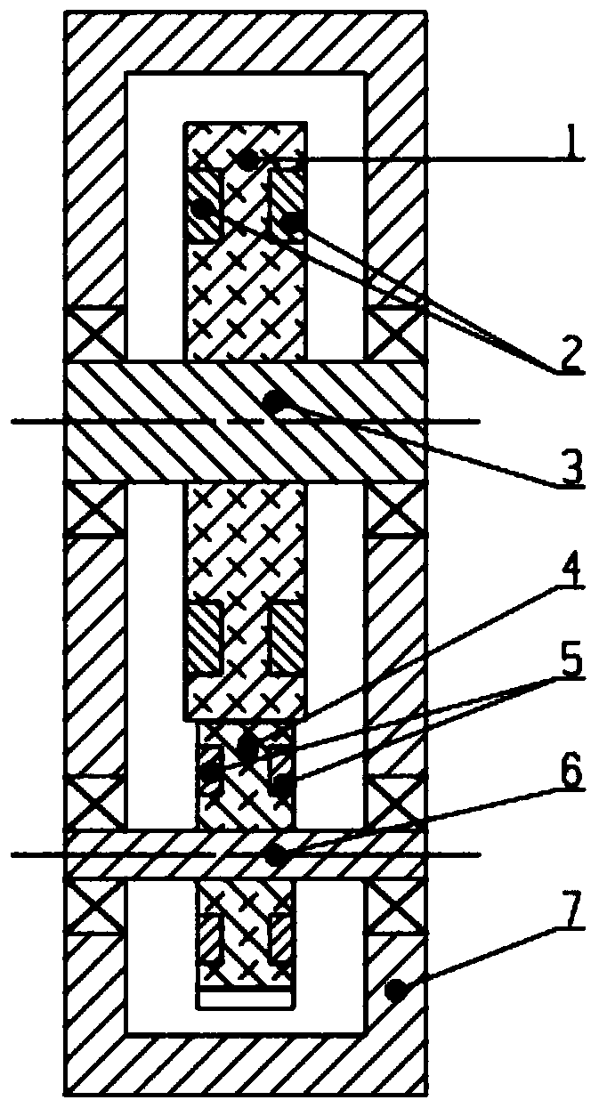
[0017] Such as figure 1 As shown, a gear dynamic anti-backlash device, the device includes a driven gear 1, a large magnet 2, a driven shaft 3, a driving gear 4, a small magnet 5, a driving shaft 6 and a base 7, and the large magnet 2 Embedded on the driven gear 1, the driven gear 1 is connected with the driven shaft 3, the small magnet 5 is embedded on the driving gear 4, the driving gear 4 is connected with the driving shaft 6, and the driven shaft 3 and the driving shaft 6 are both By the bearing being arranged on the base 7, the hole distance of the two bearing seats on the base 7 can guarantee a certain positioning accuracy during processing, and the bearing and the base hole, the shaft and the bearing adopt a clearance fit. The outer ring magnetic pole of big magnet 2 and little magnet 5 is opposite, promptly big magnet 2 adopts the magnetic pole direction of outer ring N pole (or S pole), then little magnet adopts the magnetic pole direction of outer ring S pole (or N p...


PUM


Abstract

The invention discloses a dynamic gear clearance eliminating device, belongs to the technical field of gear transmission and solves the problems of poor synchronism and complex structural design of the existing gear clearance eliminating structure. The dynamic gear clearance eliminating device comprises a driven gear (1), large magnets (2), a driven shaft (3), a driving gear (4), small magnets (5), a driving shaft (6) and a substrate (7); the large magnets (2) are embedded in the driven gear (1); the driven gear (1) is connected with the driven shaft (3); the small magnets (5) are embedded in the driving gear (4) connected with the driving shaft (6); the driven shaft (3) and the driving shaft (6) are both arranged on the substrate (7); outer ring polarities of the large magnets (2) and the small magnets (5) are opposite. The dynamic gear clearance eliminating device can be used for eliminating gear clearances dynamically, the precision of gear transmission is improved, the impact and vibration of a tooth profile are reduced, and the dynamic gear clearance eliminating device is compact in structural design, and easy to manufacture and mount, and is reduced in manufacturing and using cost.

Description

technical field [0001] The invention relates to the technical field of gear transmission, in particular to a gear dynamic anti-backlash device. Background technique [0002] Gear transmission is the most commonly used transmission method. It is a mechanical transmission that uses the teeth of two gears to mesh with each other to transmit power and motion. It has the characteristics of compact structure, high efficiency and long life. However, due to the influence of factors such as gear machining accuracy and mechanical assembly accuracy, there will be a transmission gap between the gear teeth, which will affect the transmission accuracy and bring shock vibration between the gears. For precision equipment that requires high output accuracy, it will seriously affect its performance. [0003] At present, in terms of eliminating gear transmission gaps, there are mainly two methods through mechanical structure adjustment: one is to fix the meshing gears through eccentric cente...

Claims


Application Information

Patent Timeline
Patent Type & Authority Applications(China)
IPC IPC(8): F16H55/18
CPCF16H55/18F16H55/06
Inventor 刘仲宇李嘉全李明
Owner CHANGCHUN INST OF OPTICS FINE MECHANICS & PHYSICS CHINESE ACAD OF SCI
Why Eureka
Try Eureka