Double-cavity flameless burner

A flameless combustion, double concave cavity technology, applied in the combustion chamber, combustion method, combustion equipment and other directions, can solve the problems of the complex structure of the flameless combustion chamber, no double concave cavity structure trapped vortex flameless combustion, etc. The effect of uniform temperature distribution and reduction of pollutant emissions

Active Publication Date: 2014-09-17
青岛中科国晟动力科技有限公司
View PDF7 Cites 5 Cited by
  • Summary
  • Abstract
  • Description
  • Claims
  • Application Information

AI Technical Summary

Problems solved by technology

Designing a flameless combustion chamber following the traditional combustion chamber design often requires a complex structure of the flameless combustion chamber
[0005] At present, both the University of Cincinnati in the United States and the University of Berlin in Germany have combined flameless combustion with concave cavity vortex combustion, focusing on the research of flameless combustion chambers for gas fuels, reducing thermoacoustic oscillations and increasing combustion stability through flameless combustion, but domestic There is no concave-cavity vortex flameless combustion chamber specially suitable for burning liquid fuels, and there is no research on vortex flameless combustion with a double-cavity structure at home and abroad.

Method used


Image

  • Double-cavity flameless burner
  • Double-cavity flameless burner

Examples


Embodiment Construction

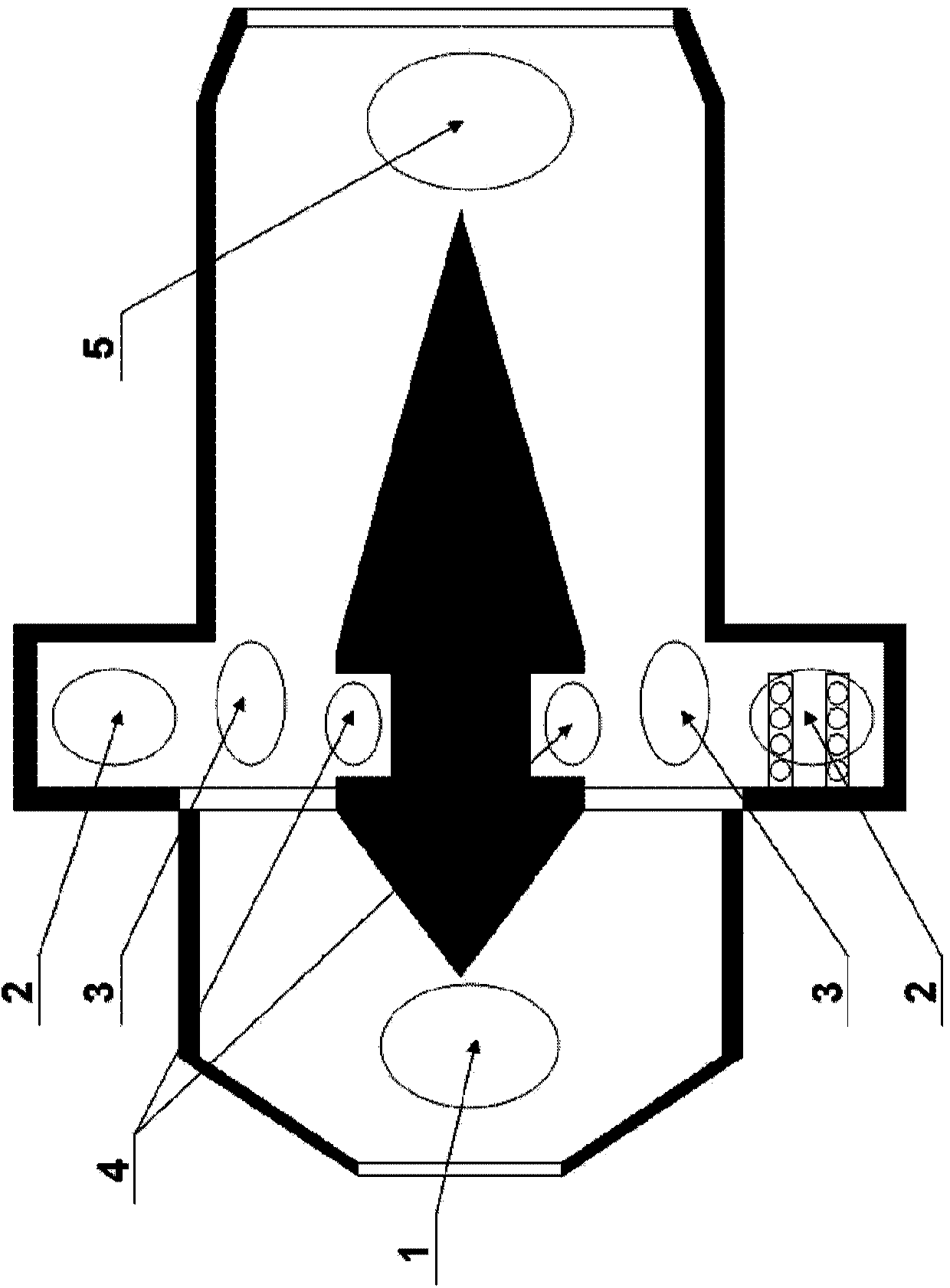
[0025] The invention combines the advantages of flameless combustion and concave cavity vortex combustion, and discloses a double concave cavity vortex flameless burner suitable for gas turbines.

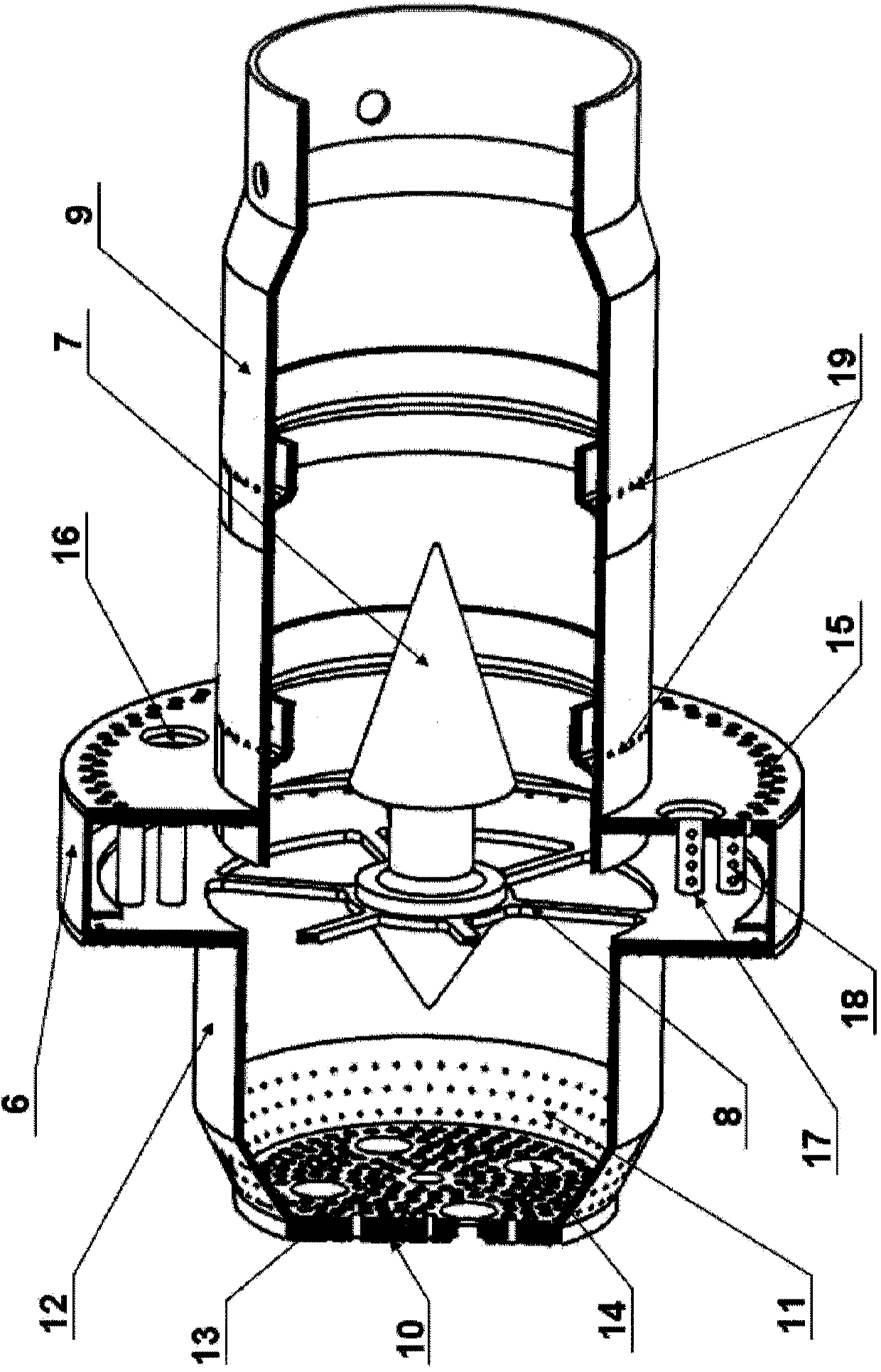
[0026] The double-cavity flameless burner of the present invention includes two areas, the main cavity and the secondary cavity. A small amount of air and fuel are sprayed into the main cavity to generate high-temperature smoke. After the high-temperature smoke flows out of the main cavity, it enters the mixed Under the disturbance of the sub-cavity area, the mixing zone is mixed with the fuel-air mixture from the head zone to achieve flameless combustion conditions, and forms flameless combustion in the downstream to achieve the purpose of reducing pollutant emissions.

[0027] The main difficulty of the present invention for the design of the known flameless burner is to realize the rapid mixing of high-temperature flue gas and fresh fuel-air mixture, so as to achieve the condition...


PUM

PropertyMeasurementUnit
Hole diameteraaaaaaaaaa

Abstract

A double-cavity flameless burner comprises a head area and a center body. The head area is provided with a top cover and a taper section. The upstream side of a main cavity is connected with the taper section of the head area through a straight tube section, and the downstream side of the main cavity is connected with a tubular outlet section. The wall of the upstream side and the wall of the downstream side of the main cavity are respectively provided with axial air jetting holes which are arranged in a staggered mode, and a plurality of fuel nozzle mounting holes are formed in the wall of the downstream side of the main cavity. The inner wall of the upstream side and the inner wall of the downstream side of the main cavity are provided with a plurality of circumferential air jetting rods, and each circumferential air jetting rod is provided with a plurality of air jetting holes in the circumferential direction. A main cavity area is formed in the area surrounded by the main cavity, and a flameless burning area is formed in the area surrounded by the outlet section. The two ends of the center body are conical, the middle of the center body is cylindrical, and the center body is fixed at the center of a cavity-free standing vortex flameless burner. The diameter of the cylindrical middle of the center body is smaller than the diameter of the conical bottom ends at the two ends of the center body, a secondary cavity area is formed between the two conical ends, and a mixing area is formed between the secondary cavity area and the main cavity area.

Description

technical field [0001] The invention belongs to the technical field of combustion chambers of gas turbines, and in particular relates to a double-cavity flameless burner, which is a combination of flameless combustion and double-cavity vortex combustion, finally realizing flameless combustion and low pollutant emission. Background technique [0002] With the strengthening of people's awareness of environmental protection, the environmental protection performance of gas turbines has become more and more prominent in various application fields of gas turbines: reducing pollution and prolonging life are the development goals of gas turbines. Traditional low-pollution combustion technology and swirler flame stabilization technology can no longer fully meet the requirements of advanced gas turbines for NO X The more and more stringent requirements are put forward for the discharge of pollutants such as pollutants. For this reason, countries all over the world have conducted exten...

Claims


Application Information

Patent Timeline
IPC IPC(8): F23R3/58
CPCY02E20/34
Inventor 崔玉峰臧鹏房爱兵邢双喜胡宏斌王昆田晓晶
Owner 青岛中科国晟动力科技有限公司
Why Eureka
Try Eureka