Light emitting device and a projection system
A technology of light-emitting device and light-concentrating system, which is applied to lighting devices, projection devices, components of lighting devices, etc. Effect
- Summary
- Abstract
- Description
- Claims
- Application Information
AI Technical Summary
Problems solved by technology
Method used
Image

Examples
Embodiment 2
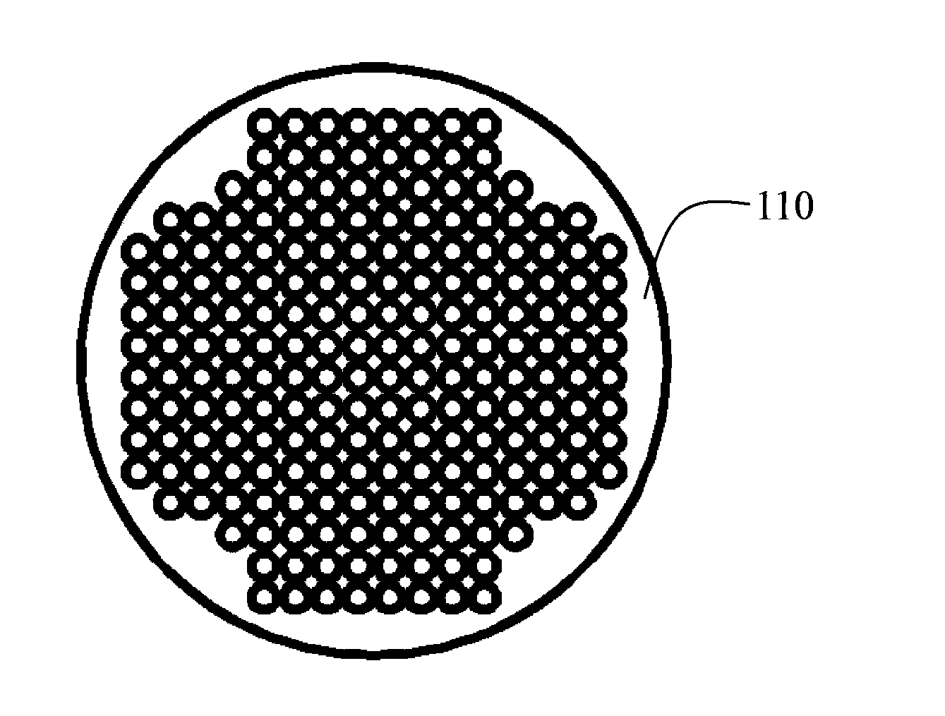
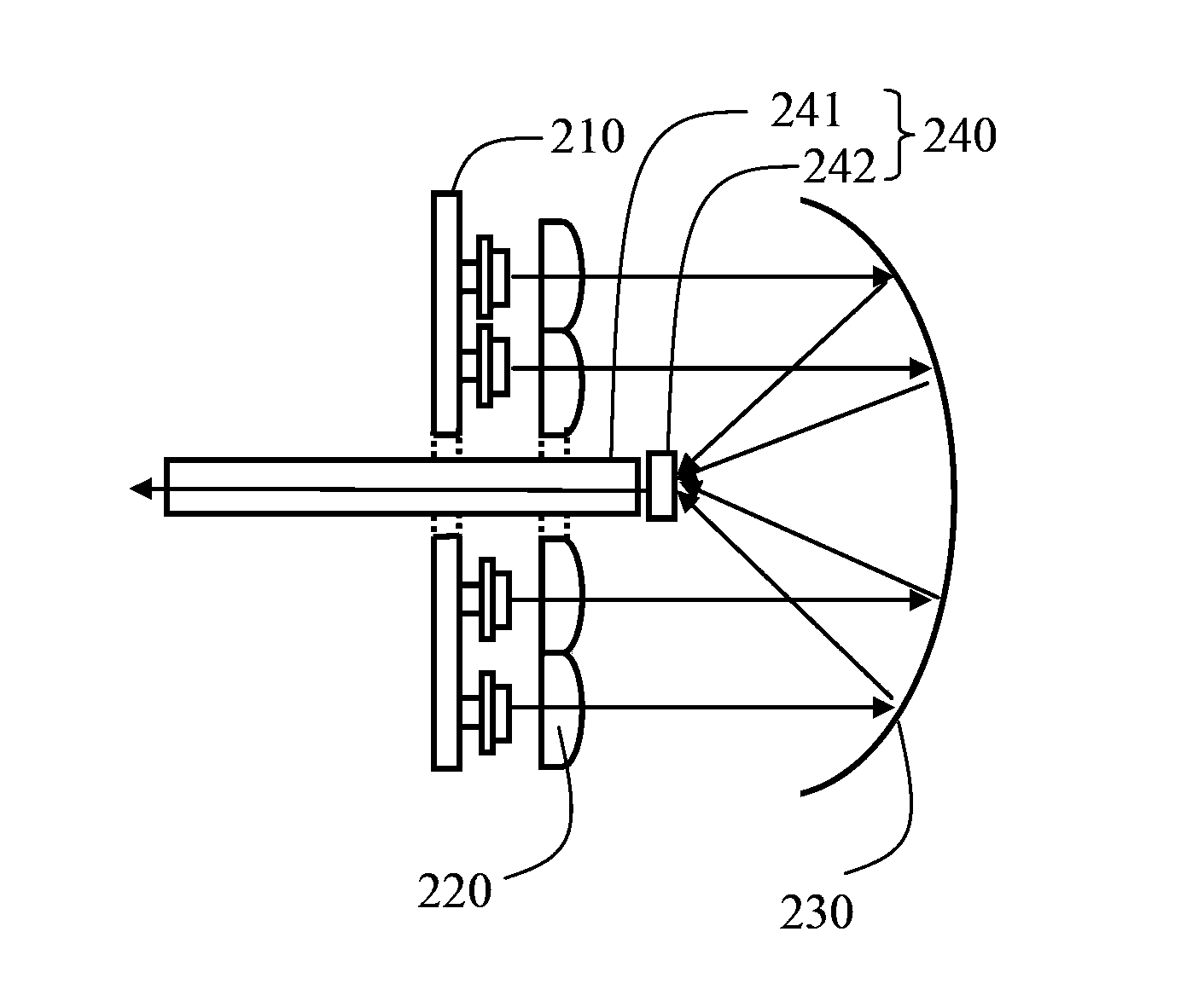
[0057] Figure 5a It is a structural front view of another embodiment of the light-emitting device of the present invention, such as Figure 5a As shown, the light emitting device includes a laser array light source 310 , a collimator lens array 320 , a reflective light collecting system 330 , and a light collecting system 340 . The light collection system 340 includes a concave lens 342 and a light dodging rod 341 . Figure 6 for Figure 5a The right view of the structure of the laser array light source shown in , as Figure 6 As shown, the laser array light source 310 includes a light-emitting area 311 and a non-light-emitting area 312 .
[0058] The difference between the light emitting device of this embodiment and the light emitting device shown in FIG. 3 lies in:
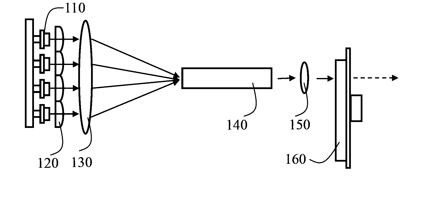
[0059] In the embodiment shown in FIG. 3 , since the light emitting surface of the laser array light source 210 is very large, the area of the reflector 230 must be large enough to collect all the emitte...
Embodiment 3
[0070] Figure 7a It is a structural front view of another embodiment of the light-emitting device of the present invention, such as Figure 7a As shown, the light emitting device includes a laser array light source 410 , a collimating lens array 420 , a reflective light collecting system 430 , and a light collecting system 440 . The light collection system 440 includes a dodging rod 441 and a concave lens 442 .
[0071] and Figure 5a Compared with the light emitting device of the illustrated embodiment, the difference of the light emitting device in this embodiment is:
[0072] (1) The reflective focusing system 430 in this embodiment is a focusing lens 431 and a reflective element 432 . Figure 8 for Figure 7a Right side view of focusing lens 431 in the illustrated embodiment, as Figure 8 As shown, the focusing lens 431 is specifically a convex lens including a hollow area 431b. The hollow area of the focusing lens 431 is a non-light-gathering area, and the non-hol...
PUM
 Abstract
Description
Claims
Application Information
 - Generate Ideas
- Intellectual Property
- Life Sciences
- Materials
- Tech Scout
- Unparalleled Data Quality
- Higher Quality Content
- 60% Fewer Hallucinations
Browse by: Latest US Patents, China's latest patents, Technical Efficacy Thesaurus, Application Domain, Technology Topic, Popular Technical Reports.
© 2025 PatSnap. All rights reserved.Legal|Privacy policy|Modern Slavery Act Transparency Statement|Sitemap|About US| Contact US: help@patsnap.com