A crash test device
A crash test and pedestal technology, applied in the direction of educational appliances, instruments, teaching models, etc., can solve the problems of complex structure of the crash test device, pollution of the test site, low utilization rate of gunpowder, etc., to improve controllability and reliability, The overall structure setting is scientific and reasonable, and the effect of reducing the impact
- Summary
- Abstract
- Description
- Claims
- Application Information
AI Technical Summary
Problems solved by technology
Method used
Image
Examples
specific Embodiment approach 1
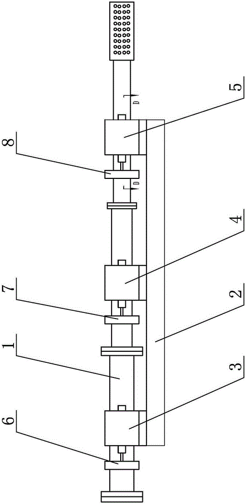
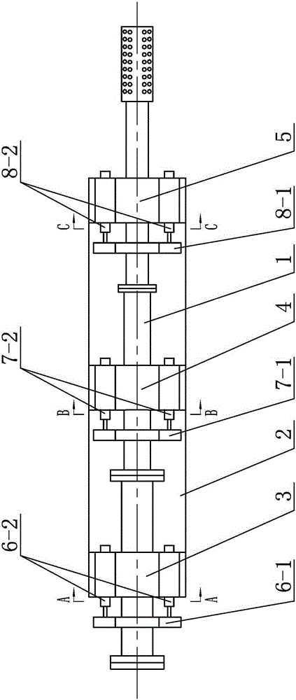
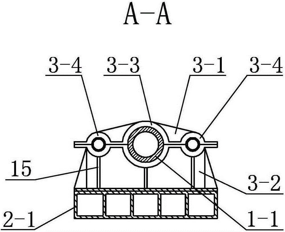
[0027] Specific implementation mode one: combine figure 1 , figure 2 , image 3 , Figure 4 , Figure 5 , Image 6 , Figure 7 , Figure 8 , Figure 9 , Figure 10 , Figure 11 , Figure 12 and Figure 13 Describe this embodiment, a crash test device described in this embodiment includes a launch tube main body 1, a workbench 2, a first base 3, a second base 4, a third base 5, and a first retreat unit 6 , the second retreat unit 7 and the re-entry unit 8, the workbench 2 is horizontally arranged and fixedly connected to the foundation 9, the first base 3, the second base 4, and the third base 5 are from left to The right is fixedly connected to the upper end surface of the workbench 2 in sequence;
[0028] The first base 3 is composed of a first upper cover body 3-1 and a first base frame body 3-2, the first upper cover body 3-1 is located directly above the first base frame body 3-2 and It is fixedly connected with the first chassis body 3-2, and a first launch ...
specific Embodiment approach 2
[0032] Specific implementation mode two: combination figure 1 , figure 2 , image 3 , Figure 4 , Figure 5 , Image 6 , Figure 7 , Figure 8 , Figure 9 , Figure 10 , Figure 11 , Figure 12 and Figure 13To illustrate this embodiment, the launch tube main body 1 in this embodiment is composed of a first component tube body 1-1, a second component tube body 1-2, a third component tube body 1-3, a locking end cover 1-4, The cartridge 1-5 and the muzzle brake 1-6 are composed of the first component tube body 1-1, the second component tube body 1-2 and the third component tube body 1-3 fixedly connected head to tail in sequence, The inner tube space of the first component tube body 1-1, the tube inner space of the second component tube body 1-2 and the tube inner space of the third component tube body 1-3 are sequentially connected to form a smoothbore structure 19, and the third component tube body One end of the 1-3 close to the re-entry unit 8 is fixedly connec...
specific Embodiment approach 3
[0033] Specific implementation mode three: combination figure 1 , figure 2 , image 3 , Figure 4 , Figure 5 , Image 6 , Figure 7 , Figure 8 , Figure 9 , Figure 10 , Figure 11 , Figure 12 and Figure 13 Describe this embodiment. In this embodiment, the first setback unit 6 includes a first lug 6-1 and two first blunt machines 6-2. The first lug 6-1 is set on the first lug 6-1. On the component tube body 1-1, a circle of first ribs 10 is processed at the contact point between the first component tube body 1-1 and the first lug 6-1 along the circumferential direction of the first component tube body 1-1, and a first A retreating machine 6-2 passes through a first retreating hole 3-4 on the first base 3 and is fixedly connected to the first lug 6-1, and another first retreating machine 6-2 passes through the first withdrawal hole 3-4. Another first withdrawal hole 3-4 on the base 3 is fixedly connected to the first lug 6-1. In this embodiment, the first retr...
PUM
 Abstract
Description
Claims
Application Information
 - R&D
- Intellectual Property
- Life Sciences
- Materials
- Tech Scout
- Unparalleled Data Quality
- Higher Quality Content
- 60% Fewer Hallucinations
Browse by: Latest US Patents, China's latest patents, Technical Efficacy Thesaurus, Application Domain, Technology Topic, Popular Technical Reports.
© 2025 PatSnap. All rights reserved.Legal|Privacy policy|Modern Slavery Act Transparency Statement|Sitemap|About US| Contact US: help@patsnap.com


