Method for reducing trailing phenomenon of liquid crystal screen and liquid crystal display device

A technology of liquid crystal display device and liquid crystal screen, which is applied to static indicators, instruments, etc., to achieve the effect of reducing the smearing phenomenon of moving images and reducing the flickering phenomenon.

Inactive Publication Date: 2014-09-17
HISENSE VISUAL TECH CO LTD
View PDF4 Cites 30 Cited by
  • Summary
  • Abstract
  • Description
  • Claims
  • Application Information

AI Technical Summary

Problems solved by technology

Although LCD TVs have made some progress in solving the problem of smearing, they cannot be fundamentally solved for a long time.

Method used


Image

  • Method for reducing trailing phenomenon of liquid crystal screen and liquid crystal display device
  • Method for reducing trailing phenomenon of liquid crystal screen and liquid crystal display device
  • Method for reducing trailing phenomenon of liquid crystal screen and liquid crystal display device

Examples


Embodiment 1

[0033] The concrete steps of this embodiment are as follows:

[0034] 1. Divide the backlight area of ​​the display screen into multiple sections; for example, it can be divided by the number of LED light strips. Assuming that the number of LED light strips is 6 from top to bottom, the backlight area can be from top to bottom The lower part is divided into 2, 3 or 6 parts. The display screen corresponding to each backlight area is also divided into 2, 3 or 6 areas.

[0035] 2. Divide the time used by one frame of image into 2, 3 or 6 time periods according to the number of segments in the backlight area;

[0036] 3. Scan each segment of the display screen in order from top to bottom (or vice versa), and at the same time turn on each backlight area in sequence of time segments.

[0037] For ease of understanding, explain with specific examples:

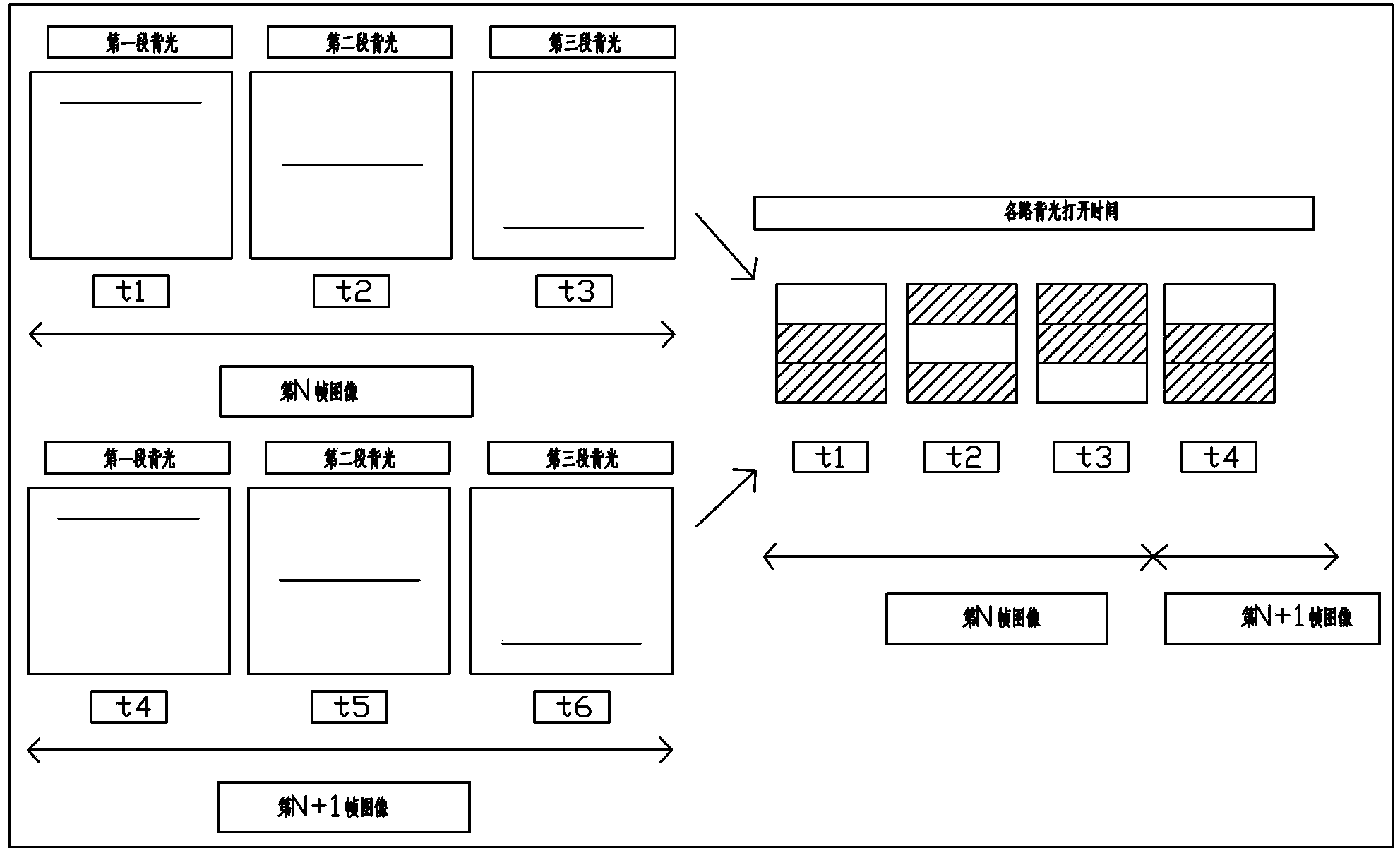
[0038] Such as figure 1 As shown, within the time of one frame of image, the screen is divided into 3 parts from top to bottom on...

Embodiment 2

[0044] Below are the concrete control steps of this embodiment:

[0045] 1. Divide the backlight area of ​​the display screen into multiple areas;

[0046] 2. Divide the time used by one frame of image into time segments, and the number of segments in the time segment is the same as the number of segments in the backlight area;

[0047] 3. In the time used by one frame of image, every time a time period passes, the corresponding backlight area segments are lit up in sequence, and the corresponding backlight area is divided into two or more points in this time period. Bright.

[0048] For ease of understanding, explain with specific examples:

[0049] Such as figure 1 As shown, within the time of one frame of image, the screen is divided into 3 parts from top to bottom on average. When the Nth frame of image is displayed, after the first backlight is turned on for the first time within t1, after a certain time delay , turn on the first segment of backlight again; after turn...

Embodiment 3

[0061] Such as Figure 4 As shown, the SOC main board sends an LVDS signal to the TCON board. When the TCON board scans to the initial position of the current segment of the LCD screen, the output synchronization signal is sent to the LED driver to turn on the corresponding segment of the LED backlight. When segmenting the LCD screen, the output synchronous signal is sent to the LED driver to turn off the LED backlight of the corresponding segment.

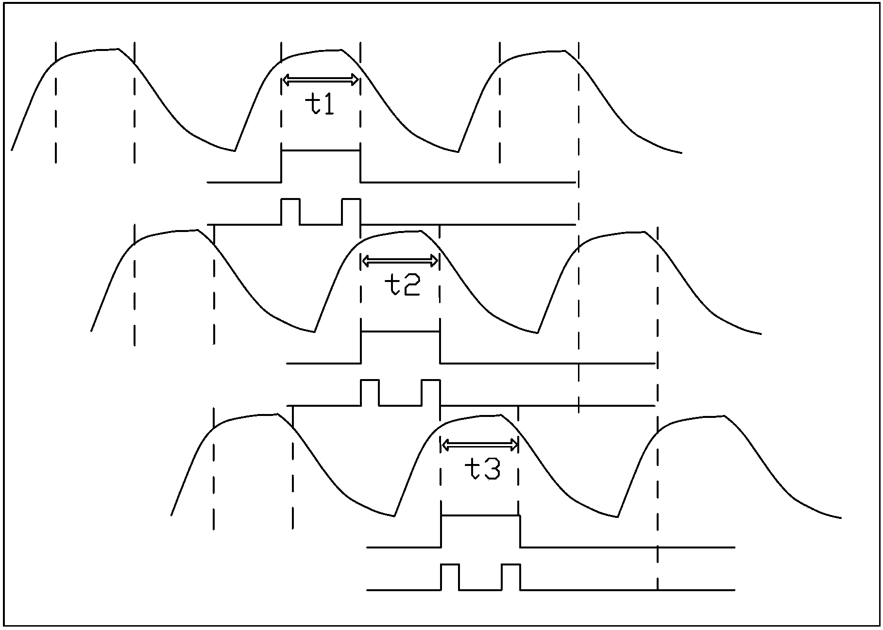
[0062] Specifically, refer to figure 1 and figure 2 As shown, within the time of one frame of image, the screen is divided into 3 parts from top to bottom on average. When the Nth frame (current frame) image is displayed, starting from time t1, the TCON board outputs a signal at the beginning of time t1 to scan the first time. The initial position of a section of LCD screen, and at the same time output a synchronous signal sent to the LED driver to turn on the corresponding first section of LED backlight; when this section of L...


PUM


Abstract

The invention discloses a method for reducing a trailing phenomenon of a liquid crystal screen and a liquid crystal display device. Therefore, a pheromone of display trailing of the existing liquid crystal screen in the prior art can be avoided. The method comprises: backlight of a backlight module group is divided into at least two segments and each segment of backlight corresponds to one segment of liquid crystal screen; and within the time for scanning one frame of image, only the segment of scanned backlight corresponding to the segment of liquid crystal screen is turned on. The device at least includes an SOC main board, a TCON board, a liquid crystal screen, an LED drive unit and LED backlight; the LED backlight is divided into multiple segments and each segment of backlight corresponds to one segment of liquid crystal screen; and the TCON board outputs a control signal, so that only the segment of scanned backlight corresponding to the segment of liquid crystal screen is turned on within the time for scanning one frame of image. According to the invention, on the basis of the segmented backlight zone mode, backlight in corresponding areas at the backlight area of the liquid crystal screen are only turned on at corresponding specific time, thereby effectively reducing the motion image trailing phenomenon of the television set.

Description

technical field [0001] The invention relates to television and image display processing technology, in particular to a method for reducing the tailing phenomenon of a liquid crystal screen and a liquid crystal display device. Background technique [0002] With the rapid development of the TV industry, people's pursuit of the visual impact effect of TV viewing is increasing day by day. Whether the images of high-speed motion can be clearly displayed is the focus of consumers' attention, and it is also the focus of R&D personnel to explore and improve. [0003] The smearing phenomenon refers to the phenomenon that the edge of the display device is hairy and the details cannot be seen clearly when displaying dynamic images. Current LCD TVs generally have tailing phenomenon, which is determined by the light-emitting principle of LCD TVs and the response time of liquid crystals. Although LCD TVs have made some progress in solving the problem of smearing, it will not be able to ...

Claims


Application Information

Patent Timeline
IPC IPC(8): G09G3/34G09G3/36
Inventor 郭思敏黄顺明孙明杨杰
Owner HISENSE VISUAL TECH CO LTD
Why Eureka
Try Eureka