Magnetic latching relay

A magnetic latching relay, magnetic steel technology, applied in electromagnetic relays, relays, detailed information of electromagnetic relays, etc., can solve the problems of large influence of magnetic field, rising cost, affecting performance, etc., to achieve uniform magnetic field strength, reasonable design, and compact structure. Effect

Active Publication Date: 2014-09-17
HAIYAN ZHONGXIN ELECTRONICS
View PDF5 Cites 1 Cited by
  • Summary
  • Abstract
  • Description
  • Claims
  • Application Information

AI Technical Summary

Problems solved by technology

[0003] The magnetic latching relay in the prior art has the following disadvantages: 1. The position of the magnetic steel assembly and the lug is unreasonable. When the ammeter is connected to the lug, the magnetic field in the ammeter will partially offset the magnetic field in the relay, making the relay in the relay The magnetic field is not uniform, which affects the performance; 2. The structure is not compact enough, which increases the cost and is not conducive to market competition; 3. The static spring combination or moving spring combination and the lug are usually connected by copper wire, which is complicated and inconvenient to install; 4 .After the components are installed, it is necessary to seal the static spring assembly and the moving spring assembly, and the sealing temperature is high, but the magnetic steel assembly will demagnetize after exceeding a certain temperature, which will affect the performance of the relay
[0004] The authorized announcement date is 2011.05.11, and the Chinese patent with the announcement number CN 201829422 U discloses a magnetic latching relay, the static spring connecting piece and the moving spring connecting piece of the magnetic latching relay are located in the vertical direction of the coil combination , when the ammeter is connected with the static spring connecting piece and the moving spring connecting piece, the magnetic field in the ammeter will partially offset the magnetic field in the relay, and it will have a greater impact on the magnetic field near the end of the yoke iron combination, making the magnetic field in the relay uneven. And the first soft copper wire is used to connect the moving spring lugs on the moving spring combination, and the second soft copper wire is used to connect the static spring lugs to the static spring combination, which will make the installation of the electric meter cumbersome and require constant adjustment of the moving spring Location of Lugs and Spring Lugs

Method used


Image

  • Magnetic latching relay
  • Magnetic latching relay
  • Magnetic latching relay

Examples


Embodiment Construction

[0022] The present invention will be further described in detail below in conjunction with the accompanying drawings and examples. The following examples are explanations of the present invention and the present invention is not limited to the following examples.

[0023] Example.

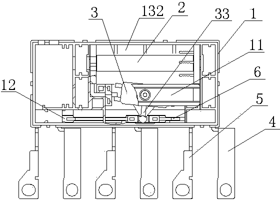
[0024] see Figure 1 to Figure 8 , The magnetic latching relay in this embodiment includes a base 1 , a yoke iron assembly 2 , a magnetic steel assembly 3 , a moving spring assembly 4 , a static spring assembly 5 and a push piece 6 .

[0025] The yoke combination 2, the moving spring combination 4 and the static spring combination 5 in this embodiment are all fixed on the base 1; a support piece 11 is fixed on the base 1, and a shaft hole is opened on the support piece 11, and the magnetic steel component 3 There is a rotating shaft on the top, and the rotating shaft fits in the shaft hole, so that the magnetic steel assembly 3 is rotatably connected to the support piece 11; the yoke assembly 2 in...


PUM


Abstract

The invention relates to a magnetic latching relay. A magnetic latching relay in the prior art easily causes a demagnetization phenomenon and is not compact in structure. The magnetic latching relay comprises a base, a yoke iron assembly, a magnetic steel assembly, a moving spring assembly, a static spring assembly and a pushing piece and is characterized in that an installing groove for installing the pushing piece is formed in the base, the length of the installing groove is larger than the pushing piece, a clamping groove is formed in the pushing piece, and a moving spring movable piece of the moving spring assembly is clamped into the clamping groove. A shifting rod for shifting the pushing piece in a reciprocating mode is arranged on the magnetic steel assembly, a limiting groove is formed in the pushing piece, and the shifting rod is clamped in the limiting groove. The pushing piece is parallel to an irony core, a moving spring terminal lug is arranged on the moving spring assembly, a static spring terminal lug is arranged on the static spring assembly, and the moving spring terminal lug and the static spring terminal lug are perpendicular to the irony core. The magnetic latching relay is simple in structure, reasonable in design, compact in structure and good in performance.

Description

technical field [0001] The invention relates to a magnetic latching relay, which is mainly applicable to the field of electronic instruments. Background technique [0002] Magnetic latching relay is an electronic control device, which plays the role of automatic adjustment, safety protection, conversion circuit, etc. in the circuit, and is widely used in power protection, automation, motion, remote control, measurement and communication devices. A magnetic latching relay usually includes a base, a yoke assembly, a magnetic steel assembly, a moving spring assembly, a static spring assembly, and a push piece. The coil is wound on the skeleton of the yoke assembly. When the current direction in the coil changes, the yoke assembly The yoke in the magnet will rotate the magnetic steel assembly, thereby pushing the push piece, so that the movable contact is separated from the static contact or closed. [0003] The magnetic latching relay in the prior art has the following disadva...

Claims


Application Information

Patent Timeline
Patent Type & Authority Applications(China)
IPC IPC(8): H01H50/02H01H50/36H01H50/18
Inventor 吴金良邓小庭施耀沈旭光
Owner HAIYAN ZHONGXIN ELECTRONICS
Why Eureka
Try Eureka