Magnetron sputtering plating film cathode device

A magnetron sputtering coating and cathode technology, which is applied in the field of magnetron sputtering coating, can solve the problems of large variation of magnetic field intensity of magnet bars, uneven film thickness, uneven magnetic field, etc., and achieves uniform cooling effect, small temperature difference, and coating The effect of improved uniformity

Active Publication Date: 2012-05-30
CSG HOLDING
View PDF0 Cites 0 Cited by
  • Summary
  • Abstract
  • Description
  • Claims
  • Application Information

AI Technical Summary

Problems solved by technology

However, the traditional magnetron sputtering coating cathode device is cooled by single-ended water inlet, the cooling water flows in from one end, and then flows out from the other end. The temperature difference between the outlet cooling water and the inlet cooling water can reach 20°C. The temperature difference between the target and the two ends of the target can also reach 20°C, so that the magnetic field strength of the magnetic rod along the length direction changes greatly, and the magnetic field is uneven. According to the principle of magnetron sputtering, argon ions bombard the atoms on the surface of the target to form a thin film. If the target temperature is low, atoms need more bombardment kinetic energy to be sputtered out, so the difference in temperature at both ends of the target will cause the thickness of the film to be uneven, thus affecting the uniformity of the coating

Method used


Image

  • Magnetron sputtering plating film cathode device
  • Magnetron sputtering plating film cathode device
  • Magnetron sputtering plating film cathode device

Examples


Embodiment Construction

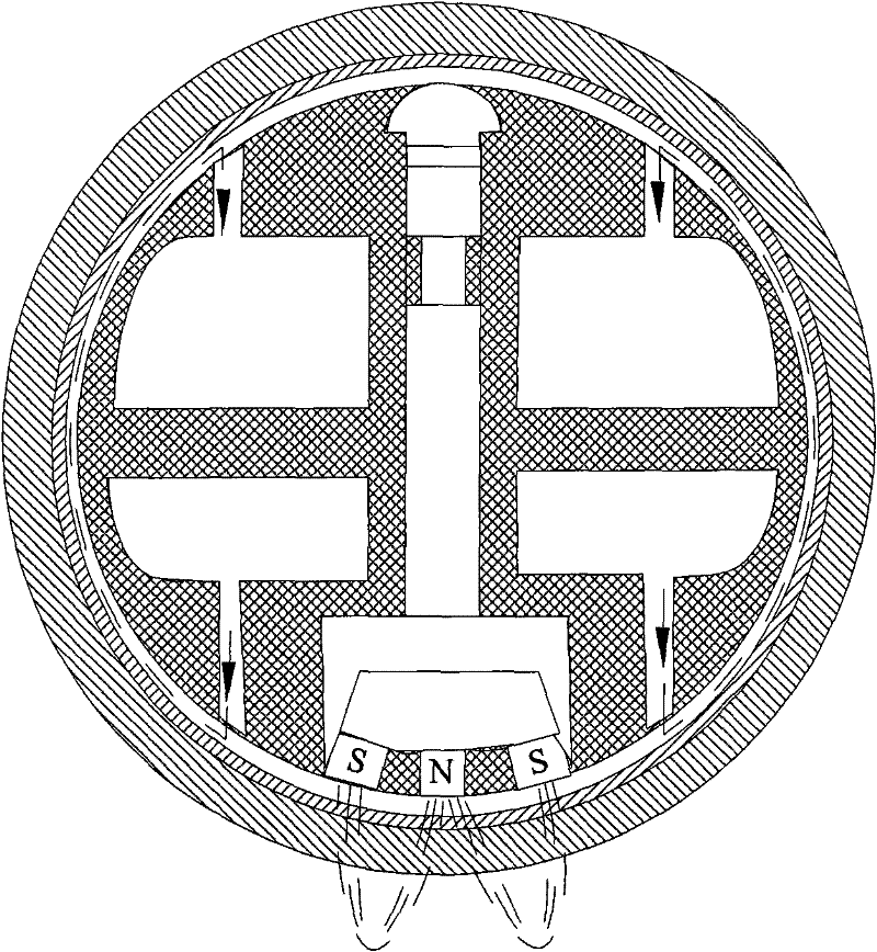
[0018] The structure of the magnetron sputtering coating cathode device (hereinafter referred to as the rotating cathode) will be mainly described below with reference to the accompanying drawings. By uniformly cooling the sputtering area, there is no temperature difference between the two ends of the target, and the magnetic field is stable during the sputtering process, which can make the coating thickness uniform.

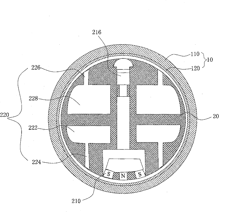
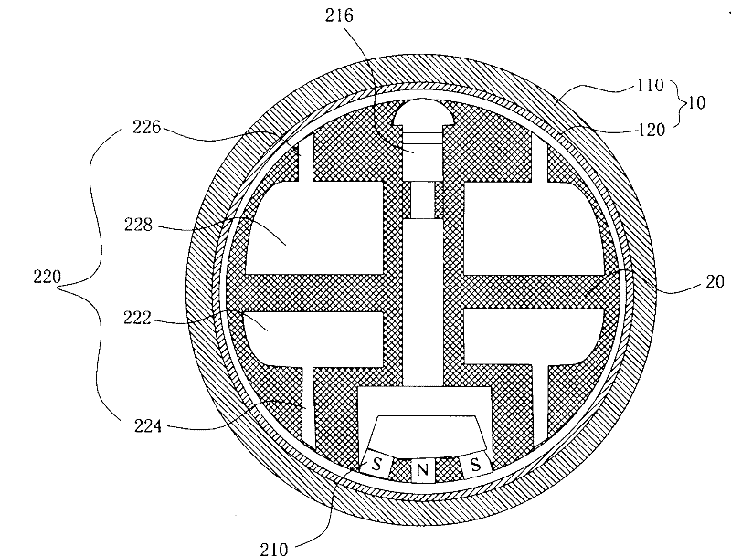
[0019] Such as figure 1 Shown is a cross-sectional view of a magnetron sputtering coating cathode device, which includes a target cylinder 10 and a magnetic rod tube 20 . The target cylinder 10 has a cylindrical structure and includes a sputtering target 110 and a target inner cylinder 120 . The sputtering target 110 evenly covers the target inner cylinder 120 and forms an integral body with the target inner cylinder 120 .

[0020] The magnetic rod pipe 20 is located in the target cylinder 10 , and a magnet 210 is installed inside the magnetic rod pipe 20 and a...


PUM


Abstract

The invention relates to a magnetron sputtering plating film cathode device which comprises a target barrel and a magnetic rod tubing, wherein the magnetic rod tubing is arranged in the target barrel. The target barrel comprises a target inner barrel and a spattering target which covers the outside surface of the target inner barrel. A magnet of a spattering magnetic field is arranged in the magnetic rod tubing, and a cooling water passage is arranged in the magnetic rod tubing. The cooling water passage comprises a water inlet passage, a plurality of water inlet holes and water return holes and a water return passage, wherein the water inlet holes and the water return holes are distributed around the magnetic field area in the length direction of the magnetic rod tubing. By arranging thewater outlet holes on the surface near the spattering area of the magnetic rod tubing, the cooling water can be uniformly sprayed to the target inner barrel from the water inlet passage through the water outlet holes. Compared with the traditional single-end water inlet cooling, the cooling effect of the cooling water in the length direction is uniform, the magnetic field strength of the cathode magnetic rod tubing has little change in length direction during rotation, and the temperature difference of the spattering target in the length direction is small, thereby obviously improving the uniformity of the plating film.

Description

【Technical field】 [0001] The invention relates to the field of magnetron sputtering coating, in particular to a magnetron sputtering coating cathode device. 【Background technique】 [0002] The cathodes used in the magnetron sputtering coating process are divided into planar cathodes and rotating cathodes according to their structural shapes. Due to the advantages of high target utilization and large loadable electric power of rotating cathodes, the use of rotating cathodes is becoming more and more extensive. The target of the rotating cathode and the target inner cylinder are fixed together to form a whole, which is generally referred to as the target cylinder. When the cathode is working, the target rotates, and the magnetic rod is fixed in the center of the target cylinder, so that the magnetic rod provides a fixed and stable The magnetic field makes sputtering stable and continuous, and the target surface can be uniformly etched. [0003] During the sputtering process, ...

Claims


Application Information

Patent Timeline
Patent Type & Authority Patents(China)
IPC IPC(8): C23C14/35
Inventor 白振中江少华
Owner CSG HOLDING
Why Eureka
Try Eureka