Twisted waveguide

A technology of waveguide and twisting, applied in the field of waveguide adapters, to achieve the effects of avoiding assembly errors, simple structure, and convenient processing

Active Publication Date: 2014-09-17
成都赛纳赛德科技有限公司
View PDF3 Cites 5 Cited by
  • Summary
  • Abstract
  • Description
  • Claims
  • Application Information

AI Technical Summary

Problems solved by technology

This twisted waveguide structure is a space curve and needs to be processed separately
At the same time, it is difficult to process the twisted waveguide and the curved waveguide as a whole with other microwave components

Method used


Image

  • Twisted waveguide
  • Twisted waveguide
  • Twisted waveguide

Examples


Embodiment 1

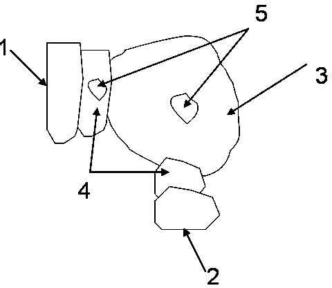
[0025] Such as figure 1 As shown, a twisted waveguide includes a coupling area 3 and two signal channels A and B connected to the coupling area 3, the signal channel A is provided with a port A1, the signal channel B is provided with a port B2, and the port A1 The normal direction at the center of and the normal direction at the center of port B2 form an included angle X, the value of X is 88 degrees, and the maximum size of port A1 on the horizontal plane is greater than the maximum size of port B2 on the horizontal plane. Here, the cross-sectional shape of the horizontal plane of the coupling region 3 is irregular.

[0026] A matching transition section 4 is provided between the port A1 in the signal channel A and the coupling area 3, and a matching transition section is provided between the port B2 in the signal channel B and the coupling area 3 paragraph 4. Here, the cross-sectional shape of the horizontal plane of the matching transition section 4 is irregular.

[002...

Embodiment 2

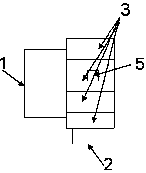
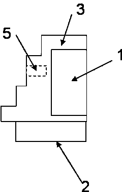
[0034] Such as figure 2 with 3 shown. Compared with Embodiment 1, the only difference is that the cross-sectional shape of the coupling region 3 on the horizontal plane is rectangular. At the same time, no matching transition section 4 and metal body 5 located thereon are provided. At the same time, the maximum depth of the coupling region 3 is more than 15% greater than the minimum depth, and the depth of the coupling region 3 gradually increases along the normal direction at the center of the port B2.

Embodiment 3

[0036] Such as Figure 4 shown. Compared with Embodiment 2, the only difference is that a matching transition section 4 is provided on the signal channel A and signal channel B respectively, and a metal body 5 is provided on the bottom of the matching transition section 4 on the signal channel A.


PUM


Abstract

The invention discloses a twisted waveguide. The twisted waveguide comprises a coupled zone, a signal channel A and a signal channel B, wherein the signal channel A and the signal channel B are communicated with the coupled zone. The signal channel A is provided with a port A, and the signal channel B is provided with a port B. An included angle X is formed between the normal of the center of the port A and the normal of the center of the port B and is larger than 20 degrees and smaller than 160 degrees. One or more matching transition sections are arranged in the signal channel A or the signal channel B. All upper surfaces of the twisted waveguide are flush with one another. One ore more metal bodies are arranged at the bottoms of the matching transition sections arranged in the signal channel A. Compared with the prior art, the twisted waveguide is simpler in structure and more convenient to machine, and assembly errors can be effectively reduced. The twisted waveguide is mainly used in communication systems, radar systems and the like with various microwave bands.

Description

technical field [0001] The present invention relates to a waveguide adapter, in particular to a waveguide adapter which makes the input and output polarization directions vertically twisted, the normal direction turns and is easy to integrate with other microwave devices. Background technique [0002] In communication and radar systems, it is often necessary to reverse the polarization direction of the rectangular waveguide by 90 degrees, and at the same time, the axis directions of the input waveguide and output waveguide need to be reversed by a certain angle. This is usually achieved using a twisted waveguide plus a bent waveguide. This twisted waveguide structure is a space curve and needs to be processed separately. At the same time, it is difficult to process the twisted waveguide and the curved waveguide as a whole with other microwave components after being connected. Contents of the invention [0003] The object of the present invention is to provide a twisted ...

Claims


Application Information

Patent Timeline
Patent Type & Authority Applications(China)
IPC IPC(8): H01P1/02
Inventor 王清源张运波
Owner 成都赛纳赛德科技有限公司
Why Eureka
Try Eureka