
Millimeter wave radial waveguide space power allocation/synthesizer

A synthesizer and waveguide technology, applied in the field of millimeter wave radial waveguide space power distribution/synthesis network, can solve the problems of the limitation of the number of synthesis channels, and achieve the effects of increased volume and weight, wide frequency range, and improved volume and weight

Active Publication Date: 2014-09-17
NO 54 INST OF CHINA ELECTRONICS SCI & TECH GRP
View PDF7 Cites 16 Cited by
  • Summary
  • Abstract
  • Description
  • Claims
  • Application Information

AI Technical Summary

Problems solved by technology

Since the U frequency band belongs to the millimeter wave frequency band, the operating frequency is quite high, and the microstrip circuit synthesis increases nonlinearly with the increase of the number of devices due to the transmission loss and the circuit structure. The number of synthesis channels is limited, and it can only be applied to chip-level power synthesis; At present, waveguide binary synthesis is the most widely used in the millimeter wave stage. Similar waveguide T-junctions, E-plane and H-plane 3dB waveguide bridges, etc., binary synthesis methods have multi-level cascading losses, and the number of synthesis channels is limited to two. In contrast, the radial waveguide power distribution / combiner can complete the synthesis of any number of solid-state power devices, and can also complete the power distribution from one radio frequency signal to any number of channels

Method used


Image

  • Millimeter wave radial waveguide space power allocation/synthesizer
  • Millimeter wave radial waveguide space power allocation/synthesizer
  • Millimeter wave radial waveguide space power allocation/synthesizer

Examples


Embodiment Construction

[0015] The present invention will be further described in detail below in conjunction with the accompanying drawings and specific embodiments.

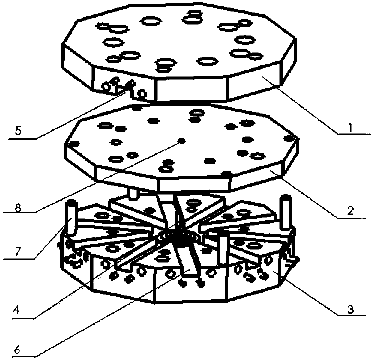
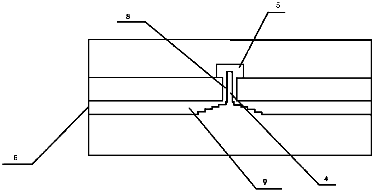
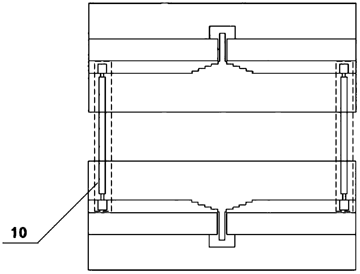
[0016] like Figure 1-2 As shown, the radial waveguide power divider / combiner of the present invention includes an upper cavity 1, a middle cavity 2 and a lower cavity 3 assembled sequentially from top to bottom, and the three cavities are positioned and assembled with pins 7, A standard waveguide cavity 5 is opened in the upper cavity, one end of the standard waveguide cavity 5 is located at the center of the upper cavity, and the other end of the standard waveguide cavity 5 is located at the edge of the upper cavity 1; A plurality of radial waveguide cavities 6, a multi-step matching pin 4 is arranged in the center of the lower cavity; a round hole 8 is opened in the center of the middle cavity 2; the free end of the multi-step matching pin 4 passes through the round hole 8 and It is located in the standard waveguide cavity 5 in th...


PUM


Abstract

The invention discloses a millimeter wave radial waveguide space power allocation / synthesizer which comprises an upper cavity, a middle cavity and a lower cavity which are assembled sequentially from top to bottom. A standard waveguide cavity is formed in the upper cavity, one end of the standard waveguide cavity is located in the center of the upper cavity, and the other end of the standard waveguide cavity is located in the edge of the upper cavity. A plurality of radial waveguide cavities which are evenly distributed are formed in the lower cavity, and the center of the lower cavity is provided with a multistage ladder matching pin. The center of the middle cavity is provided with a circular hole. The free end of the multistage ladder matching pin penetrates through the circular hole and is located in the standard waveguide cavity in the center of the upper cavity. A gap is reserved between the multistage ladder matching pin and the circular hole. According to the millimeter wave radial waveguide space power allocation / synthesizer, the operation bandwidth of the radial waveguide power allocation / synthesizer is broadened through the multistage ladder matching pin, and the synthetic efficiency in multiplex synthesis is greatly improved compared with that of a traditional technology.

Description

technical field [0001] The invention relates to a millimeter wave radial waveguide space power distribution / synthesis network. Background technique [0002] Millimeter-wave broadband high-power amplifiers are increasingly used in navigation, precision guidance, radar, communications, and electronic countermeasures. In order to obtain high power output of millimeter waves, it is necessary to use power synthesis to place multiple solid-state power devices in a power synthesis amplifier; on the other hand, for economical and reliability considerations, usually a smaller The solid-state power device performs power synthesis to replace a high-power solid-state power device. In addition to being able to output more power, the power synthesis technology can also ensure that the power amplification system continues to work in the event of one or part of the solid-state power devices failing. Complete failure, just system performance degradation. [0003] The research focus is to d...

Claims


Application Information

Patent Timeline
Patent Type & Authority Applications(China)
IPC IPC(8): H01P5/12
Inventor 李硕
Owner NO 54 INST OF CHINA ELECTRONICS SCI & TECH GRP
Learn More