Dynamic voltage restorer compensation control method based on minimum active power injection

A technology of dynamic voltage recovery and active power, applied in the direction of AC network voltage adjustment, AC network load balancing, etc., can solve the problems of load voltage phasor phase jump, mathematical derivation fuzzy, energy consumption, etc., to ensure reliable power supply performance, reduce active power, and reduce energy loss

Active Publication Date: 2014-09-17
SHENZHEN CITY SAMKOON TECH
View PDF3 Cites 15 Cited by
  • Summary
  • Abstract
  • Description
  • Claims
  • Application Information

AI Technical Summary

Problems solved by technology

[0005] At present, there are three main control strategies used by DVR devices: full compensation control strategy, non-inverting compensation control strategy and minimum energy compensation control strategy. Although both the full compensation control strategy and the same-phase compensation control strategy can better compensate the system when the voltage sag occurs The voltage required by the load, but the DVR device needs to inject a large amount of active power into the system when performing compensation work, and consumes more energy
The traditional minimum energy compensation control strategy theory is relatively complicated. When determining the conditions for DVR devices to achieve minimum energy compensation, it needs to be discussed on a case-by-case basis, and the mathematical derivation is fuzzy. In addition, there may be problems such as phase jumps in the load voltage phasor after compensation.

Method used


Image

  • Dynamic voltage restorer compensation control method based on minimum active power injection
  • Dynamic voltage restorer compensation control method based on minimum active power injection
  • Dynamic voltage restorer compensation control method based on minimum active power injection

Examples


Embodiment Construction

[0021] The present invention will be described in further detail below in conjunction with the accompanying drawings.

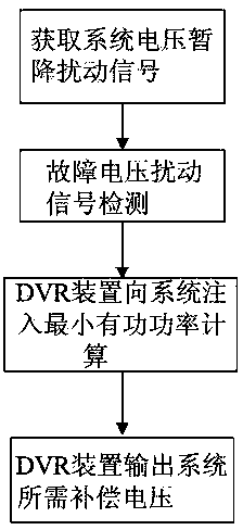
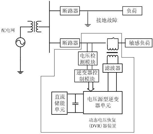
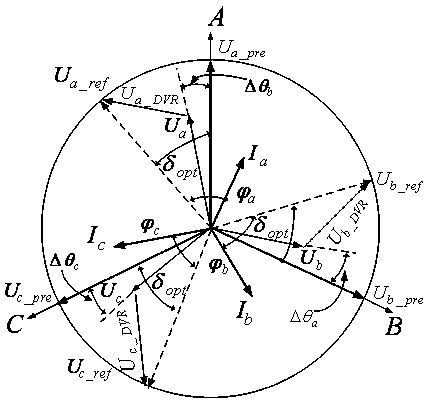
[0022] The present invention is based on the dynamic voltage restorer compensation control method based on the minimum active power injection. By analyzing the active power consumed by the DVR device when compensating for the voltage sag disturbance in the distribution network, the system voltage and the DVR device after the sag disturbance occur are analyzed. Deduce the relationship between the compensation voltage injected into the system, the load reference voltage, and the load current, establish the system vector diagram and the active power characteristic equation when the DVR device is working, derivate the equation, and use the derivative knowledge to determine the DVR device in the system. The conditions to be met when the minimum active power is injected to compensate the load voltage, thereby effectively prolonging the compensation time of the DVR d...


PUM


Abstract

The invention discloses a dynamic voltage restorer compensation control method based on minimum active power injection. The method comprises the steps that the amplitude and phases of a three-phase voltage of a power distribution network system are obtained; the system voltage of a power distribution network which is subjected to voltage sag is detected and analyzed, and the characteristic quantity of a voltage sag signal is determined; the relations between the system voltage, a load reference voltage and a compensating voltage before and after the voltage sag happens are deduced and analyzed, an active power characteristic equation is established and subjected to derivation, and the conditions required by a dynamic voltage restorer for injecting minimum active power compensation load voltage into the system are determined; when the conditions are met, the system sends a compensation instruction to an inverter, and the inverter outputs the voltage required by the compensation system. By means of the dynamic voltage restorer compensation control method based on minimum active power injection, detection and compensation of a fault voltage can be conducted accurately in time, the active power injected into the system in the operating process of a DVR device can be lowered to the maximum extent, energy consumption of a direct-current energy storage unit of the DVR device is lowered, and compensation time is effectively prolonged.

Description

technical field [0001] The invention relates to a dynamic voltage restorer compensation control method based on minimum active power injection, which belongs to the field of analysis of transient power quality disturbance signals, and is particularly suitable for detection and compensation of short-term voltage disturbances in distribution networks. Background technique [0002] Since the 1980s, some new power electronic loads have continuously increased the requirements for power quality, and power quality has become a common concern of power companies and users. Among the many problems of power quality, the damage caused by transient voltage disturbance, including temporary voltage drop, rise, flicker, etc., is the most common. Statistics show that for large-scale power users, the annual occurrence rate of voltage sags exceeding 20% ​​is about 10-20 times. In important places such as airports, banks, precision electronic component manufacturing, computer networks, and serv...

Claims


Application Information

Patent Timeline
Patent Type & Authority Applications(China)
IPC IPC(8): H02J3/12H02J3/28
Inventor 黄永红徐俊俊孙玉坤刘国海
Owner SHENZHEN CITY SAMKOON TECH
Why Eureka
Try Eureka