
Drive circuit device

A technology for driving circuits and circuit substrates, which is applied in the direction of circuit devices, circuit heating devices, circuits, etc., and can solve problems such as miniaturization restrictions

Inactive Publication Date: 2014-09-17
JTEKT CORP
View PDF8 Cites 2 Cited by
  • Summary
  • Abstract
  • Description
  • Claims
  • Application Information

AI Technical Summary

Problems solved by technology

However, in the structure in which the switching element is mounted on one side of the circuit board as in the above-mentioned Japanese Patent Application Laid-Open No. 2009-277726, since it is necessary to secure a mounting area on the circuit board, there is a limit to its miniaturization.

Method used


Image

  • Drive circuit device
  • Drive circuit device
  • Drive circuit device

Examples


Embodiment Construction

[0018] Hereinafter, one embodiment of the present invention will be described with reference to the drawings.

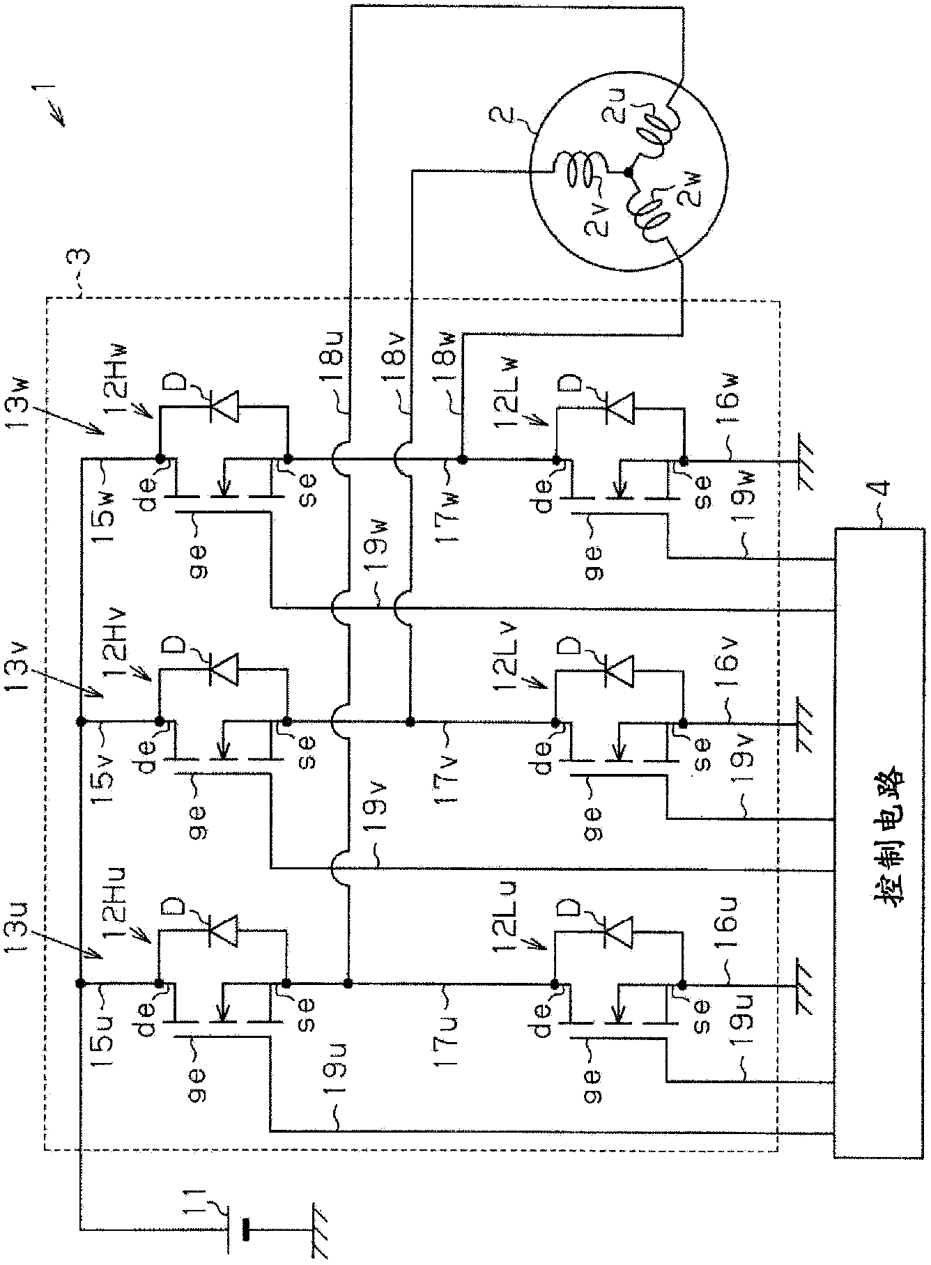
[0019] figure 1 The illustrated drive circuit device 1 supplies drive power to an electric motor 2 used as a drive source of an electric power steering system that applies assist force to a steering system. As shown in the figure, the drive circuit device 1 includes a drive circuit 3 that supplies drive power to the electric motor 2 and a control circuit 4 that controls the operation of the drive circuit 3 . The drive circuit device 1 of the present embodiment is configured as a motor control unit (ECU). In addition, as the electric motor 2 of this embodiment, the brushless motor which has three phases (U phase, V phase, W phase) is used.

[0020] The drive circuit 3 has upper-stage FETs (field-effect transistors) 12Hu, 12Hv, and 12Hw as first switching elements connected to the vehicle power supply (battery) 11 , and lower-stage FETs 12Lu, 12Lv, and 12Lw as second...


PUM


Abstract

The invention provides a drive circuit device. The drive circuit device includes a circuit board (21) having a multilayer structure, which includes first to fourth circuit conductor layers (31a to 31d), and first to third insulating layers (32a to 32c) ; and heat sinks (22, 23) that dissipate heat of the circuit board (21) to an outside. An upper FET (12Hu) state is embedded in the first insulating layer (32a), and a lower FET (12Lu) state is embedded in the second insulating layer (32b). The upper FET (12Hu) and the lower FET (12Lu) are disposed so that a region in which the upper FET (12Hu) is positioned and a region in which the lower FET (12Lu) is positioned overlap each other in a stacking direction. A lead-out portion (41) is formed at a second circuit pattern (33b) of the circuit conductor layer (31b), the lead-out portion (41) extending from the circuit board in a direction orthogonal to the stacking direction, and being connected to the heat sinks so that heat is transferred to the heat sinks.

Description

[0001] This application claims the priority of Japanese Patent Application No. 2013-047828 filed on March 11, 2013, and uses the entire contents including the specification, drawings, and abstract here. technical field [0002] The invention relates to a drive circuit arrangement. Background technique [0003] Generally, supply of drive power to an electric motor is performed using a drive circuit (inverter) in which switching arms having switching elements such as FETs connected in series are connected in parallel. [0004] Conventionally, there is known a drive circuit device (motor control device) having such a drive circuit using a multi-layered circuit conductor layer in which an insulating layer is interposed between a plurality of circuit conductor layers formed with a circuit pattern. layer structure of the circuit board, thereby realizing its miniaturization, etc. For example, refer to JP-A-2009-277726. [0005] However, since a large drive current for driving the...

Claims


Application Information

Patent Timeline
Patent Type & Authority Applications(China)
IPC IPC(8): H02M7/00H05K7/20
CPCH05K1/0263H01L23/367H05K1/185H01L23/13H01L23/3675H02M7/003H05K2201/10166H05K7/209H05K1/0203H01L2924/0002H01L2924/00
Inventor 内田修弘
Owner JTEKT CORP
Learn More