
Automated Motor Control

A technology of controller and current reduction, applied in the direction of motor generator control, electronic commutation motor control, current controller, etc., can solve the problems of increasing the controller, reducing the system performance, increasing the complexity of the gain design, etc.

Active Publication Date: 2014-09-17
TEXAS INSTR INC
View PDF5 Cites 19 Cited by
  • Summary
  • Abstract
  • Description
  • Claims
  • Application Information

AI Technical Summary

Problems solved by technology

Unnecessarily increasing the number of controllers not only increases the complexity of gain design, but also degrades system performance

Method used


Image

  • Automated Motor Control
  • Automated Motor Control
  • Automated Motor Control

Examples


Embodiment Construction

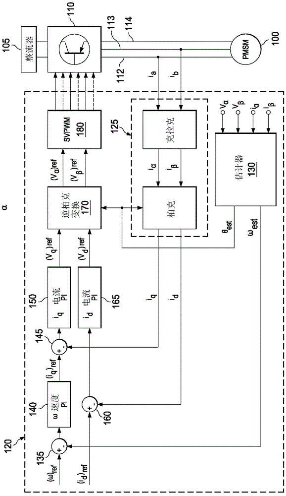
[0017] Referring now to the drawings, and specifically to FIG. 1 , a prior art scheme for motor control is depicted to help illustrate the advancements described herein. In Figure 1, a PMSM 100 is controlled by using a conventional PI-based field-oriented control scheme. The rectifier 105 provides power to the inverter 110 . The inverter 110 includes various gates or switches to extract power from the rectifier 105 and apply power to the current paths 112 , 113 , 114 of the three windings of the motor 100 . The inverter 110 is controlled by receiving a control signal from the control device 120 . The current of the motor 100 (i a and i b ) is sensed and transformed by using a known mathematical transformation, the Clarke-Park transformation (Clarke-Park transformation) 125, to obtain the feedback value i q and i d . Estimator 130 extracts the available motor current (i α and i β ) and the applied voltage (V α and V β ) value and output the estimated rotor position θ ...


PUM


Abstract

Input-output linearization (IOL) and extended state observer (ESO) techniques are applied to a Field Oriented Control (FOC) for Permanent Magnet Synchronous Motors (PMSM). In one such approach, at least one gain value is determined based at least in part on a given bandwidth value. Operating parameters for the motor are determined based on the at least one gain value and information from a current sensor regarding motor current. Control signals used to the control the motor are determined based on the determined operating parameters. Accordingly, automated control can be effected through setting a bandwidth value through the implementation of IOL and ESO techniques.

Description

technical field [0001] This invention relates generally to motor controllers and, more particularly, to controlling motors with improved automation aspects. Background technique [0002] Various types of electric motors are well known. Generally speaking, electric motors are driven by applying current to the input terminals of the motor, where the current creates a magnetic field that interacts with another magnetic field to turn the motor rotor. For example, one or more permanent magnets can provide a magnetic field that interacts with the magnetic field generated by the input current. The rotation of the motor can be controlled by controlling various aspects of the current applied to the motor. [0003] Motors come in a variety of designs. A common design consists of having three windings of wire through which current flows, where the magnetic field generated by the current flow interacts with a number of permanent magnets. In order to control motors with complex desig...

Claims


Application Information

Patent Timeline
Patent Type & Authority Applications(China)
IPC IPC(8): H02P21/13
CPCH02P21/0003H02P21/13H02P6/28
Inventor A·S·卡塔瑞亚D·P·麦吉
Owner TEXAS INSTR INC
Learn More