Gearbox Control Module

A transmission control and control module technology, which is applied in the direction of transmission control, providing connectors, printed circuit boards, electrical components, etc., can solve the problems of high cost and multiple construction spaces, and achieve low cost, low wiring cost, and reduced assembly The effect of consumption

Inactive Publication Date: 2014-09-17
ROBERT BOSCH GMBH
View PDF4 Cites 3 Cited by
  • Summary
  • Abstract
  • Description
  • Claims
  • Application Information

AI Technical Summary

Problems solved by technology

However, the disadvantage arises that the additional controller requires more construction space in the engine compartment and that it is more complex to route the electrical lines from the outside to the sensors and actuators located inside the transmission

Method used


Image

  • Gearbox Control Module
  • Gearbox Control Module
  • Gearbox Control Module

Examples


Embodiment Construction

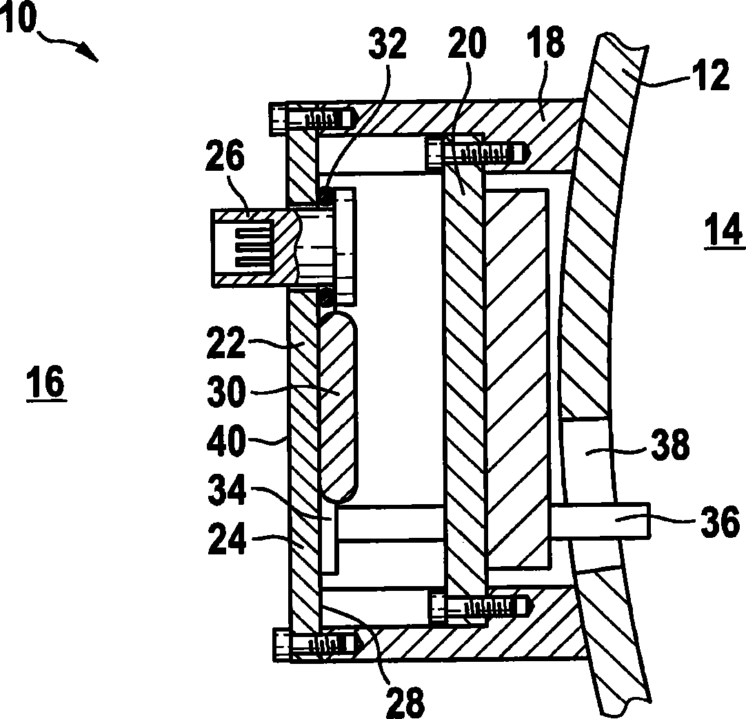
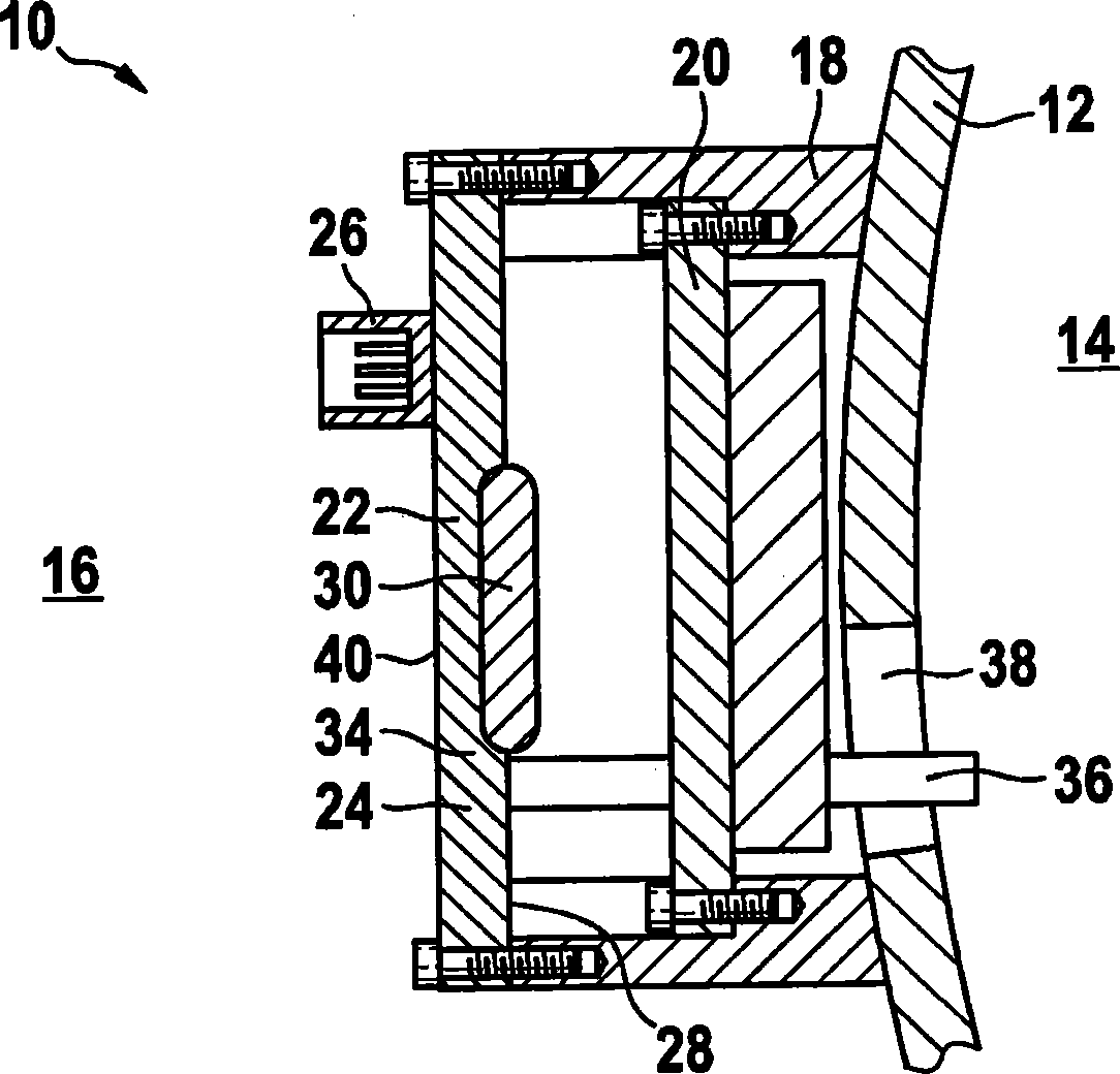
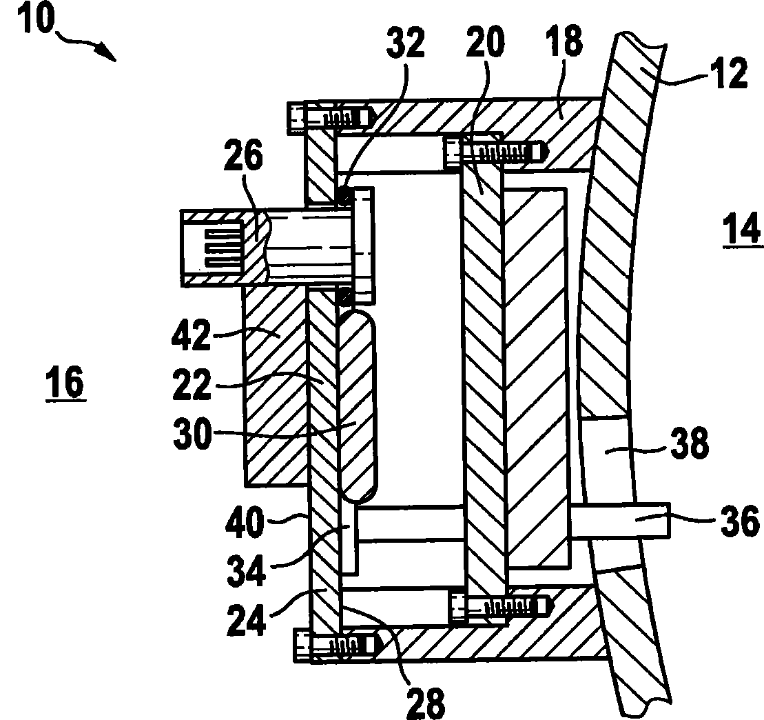
[0035] figure 1 A section of a transmission 10 is shown, which is surrounded by a transmission housing 12 . The transmission housing 12 separates an interior 14 of the transmission 12 from an engine compartment 16 .

[0036] The transmission housing 12 includes a two-stage flange 18 within which a hydraulic control module 20 is disposed. The hydraulic control module 20 is seated on the inner protrusion of the flange 18 and screwed to the flange 18 there. The transmission 10 can be hydraulically actuated via a hydraulic control module 20 arranged inside the transmission housing 12 . Instead of hydraulic actuation, electromechanical actuation systems can also be used for the transmission.

[0037] The transmission control module 22 is projected onto the outside of the flange 18 and screwed to the flange 18 .

[0038] The transmission control module 22 comprises a carrier plate 24 in which a transmission insert 26 is integrated and on its inside 28 an electronic unit (TCU) 30...


PUM


Abstract

A gearbox control module (22) for a gearbox (10) comprising an electronic component (30) with an electronic circuit for controlling the gearbox, electrical connections (34) and a module carrier (24), on which the electronic component (30) and the electrical connections (34) are mounted. The module carrier (24) is designed as a cover for sealing closure of a gearbox interior (14).

Description

technical field [0001] The invention relates to a transmission control module and a transmission for a vehicle. Background technique [0002] An electronic control unit is used to control the automatic transmission, which can be arranged inside the transmission housing (integrated control unit) or mounted externally on the transmission housing (additional control unit). [0003] An additional controller can have the advantage over an integrated controller that it withstands lower temperatures and can be constructed economically. However, the disadvantage arises that the additional control unit requires more installation space in the engine compartment and that it is more complex to route electrical lines from the outside to the sensors and actuators located inside the transmission. [0004] The integrated controller is designed in principle as a so-called electronic control module and can contain electronic circuits or electronic components ("transmission control unit (tran...

Claims


Application Information

Patent Timeline
Patent Type & Authority Applications(China)
IPC IPC(8): H05K5/00F16H61/00
CPCH05K5/0082Y10T74/2003F16H61/0006F16H61/0202
Inventor P·茨魏格勒H·布劳恩M·基歇尔
Owner ROBERT BOSCH GMBH
Why Eureka
Try Eureka