Progressive broaching device for processing internal gear ring

A technology for internal gears and equipment, applied in the field of metal cutting, can solve problems such as inappropriate production of large diameters, difficulties in manufacturing broaches, poor rigidity of broaches, etc., to facilitate assembly and transportation, improve cutting efficiency and cutting accuracy, and manufacture easy effect

Inactive Publication Date: 2014-09-24
TAIZHOU LIHUA GEAR MFG
View PDF1 Cites 4 Cited by
  • Summary
  • Abstract
  • Description
  • Claims
  • Application Information

AI Technical Summary

Problems solved by technology

For example, broaching an internal ring gear with a diameter of Φ200mm and a modulus of 4mm requires a broach with a length of about 3m to reasonably share the cutting amount, and it is difficult to manufacture a broach with a length of 3m. The rigidity itself is poor, and the strength is also very low. The ultra-slender broach cannot be used for production at all, so the broaching process is not suitable for making large-diameter and large-modulus internal gears, and is only suitable for broaching small-sized and small-modulus internal gears. Ring gear

Method used


Image

  • Progressive broaching device for processing internal gear ring
  • Progressive broaching device for processing internal gear ring
  • Progressive broaching device for processing internal gear ring

Examples


Embodiment 1

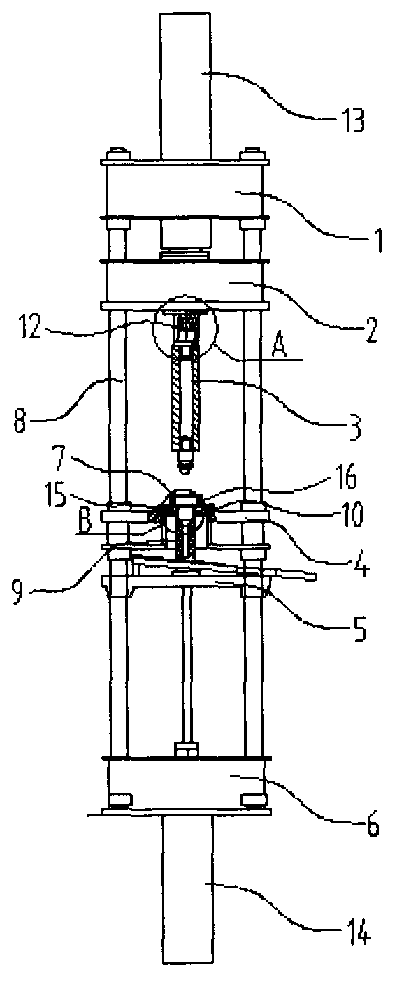
[0027] Example 1: see figure 1 As shown in the figure, a push-cutting equipment for processing an internal gear ring includes an upper fixed table 1, an upper movable pressing table 2, a pushing knife 3, a fixed work table 4, a lower movable top seat 5 and a lower Pedestal 6.

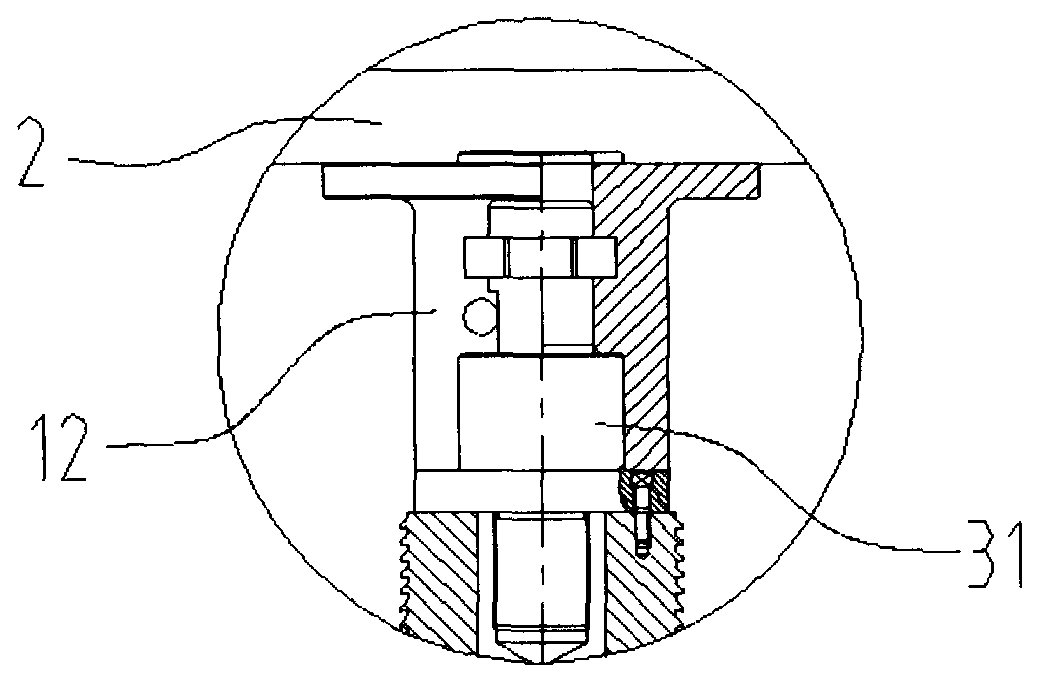
[0028] The upper fixed table 1, the fixed work table 4 and the lower base 6 are connected by four uprights 8, and the upper movable pressing table 2 and the lower movable top seat 5 are all slidably connected with the four uprights 8, and the pushing The knife 3 is detachably connected below the upper movable pressing table 2 , and the upper end of the lower movable top seat 5 is fixedly provided with a knife receiving seat 9 .

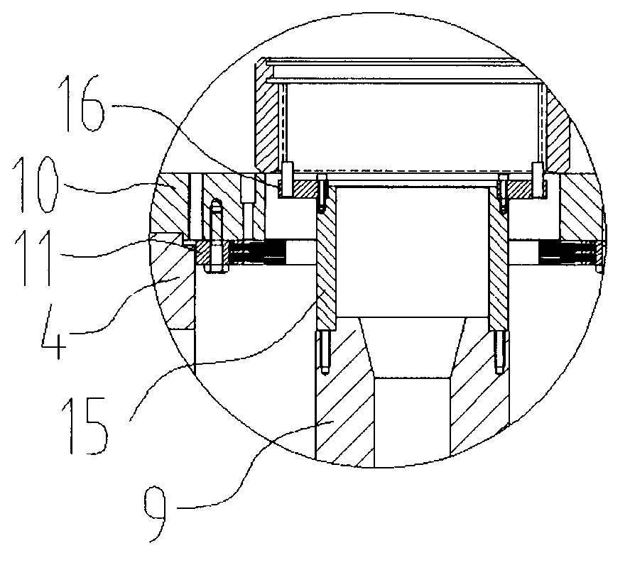
[0029] like Figure 4 , Figure 5 As shown, the lower end of the pusher 3 is provided with a tool centering cone surface 30 , and the upper end of the tool receiving seat 9 is provided with a concave tool seat centering cone surface 30 that cooperates with the tool centering...


PUM


Abstract

The invention discloses a progressive broaching device for processing an internal gear ring. The device comprises an upper fixing platform, an upper movable pressing platform, a push broach, a fixing working platform, a lower movable top seat and a lower base arranged from top to bottom, wherein the internal gear ring is arranged on the fixing working platform; the upper fixing platform, the fixing working platform and the lower base are connected through four vertical columns; the upper movable pressing platform and the lower movable top seat are connected with the four vertical columns in a sliding manner; the push broach is connected onto the lower part of the upper movable pressing platform in a separate-type manner; a cutter receiving seat is fixedly arranged at the upper end of the lower movable top seat. According to the invention, through utilizing the device for progressive broaching the gear part of the internal gear ring, the cutting efficiency and the cutting precision are improved, and the manufacturing cost is reduced.

Description

technical field [0001] The invention belongs to the technical field of metal cutting processing, and particularly relates to a push cutting device for processing an inner gear ring. Background technique [0002] The inner gear installed on the rear axle of heavy-duty vehicles is a transmission part that bears heavy loads and is a key component in the transmission system of the vehicle. The technical requirements of the inner gear ring are high, and the manufacturing is difficult. It must be processed by precision cutting to meet the design requirements. There are many ways to process the inner gear ring, and the commonly used machining processes are the plunger cutting process, the broaching process and the push cutting process. The plunging process is one of the metal cutting processes with low production efficiency. Under normal circumstances, it takes 60 to 70 minutes to process a ring gear of about Φ200mm. This production efficiency obviously does not meet the requireme...

Claims


Application Information

Patent Timeline
IPC IPC(8): B23F5/28B23F21/26
Inventor 李志斌柳玉龙宋森林
Owner TAIZHOU LIHUA GEAR MFG
Why Eureka
Try Eureka