Eureka AIR delivers breakthrough ideas for toughest innovation challenges, trusted by R&D personnel around the world.

Automobile brake disc cutting precision control mechanism

A precision control and automobile braking technology, which is applied in the direction of automatic control devices, manufacturing tools, metal processing machinery parts, etc., can solve the problems of scratches on the surface of metal debris, repeated cutting on the surface, and reduced surface accuracy, so as to improve the cutting efficiency. Improve efficiency and cutting accuracy, improve machining accuracy, and prevent scratches

Inactive Publication Date: 2021-02-05
胡美芳
View PDF0 Cites 0 Cited by
  • Summary
  • Abstract
  • Description
  • Claims
  • Application Information

AI Technical Summary

Problems solved by technology

[0003] During the processing of the brake disc, it is necessary to cut the surface with a certain precision. However, the existing cutting device lacks the problem of precision control. Repeated cutting will result in lower surface accuracy, and the falling of metal debris after cutting will easily cause scratches on the surface after cutting
[0004] To this end, a car brake disc cutting precision control mechanism is provided to solve the problem of precision control of brake disc machining and waste recycling.

Method used


Image

  • Automobile brake disc cutting precision control mechanism
  • Automobile brake disc cutting precision control mechanism
  • Automobile brake disc cutting precision control mechanism

Examples


Embodiment Construction

[0023] The following will clearly and completely describe the technical solutions in the embodiments of the present invention with reference to the accompanying drawings in the embodiments of the present invention. Obviously, the described embodiments are only some, not all, embodiments of the present invention. Based on the embodiments of the present invention, all other embodiments obtained by persons of ordinary skill in the art without making creative efforts belong to the protection scope of the present invention.

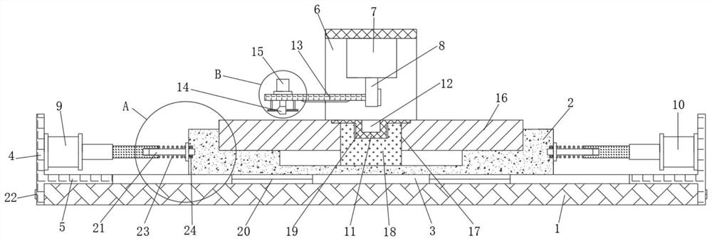
[0024] see Figure 1 to Figure 4 , the present invention provides a technical solution:

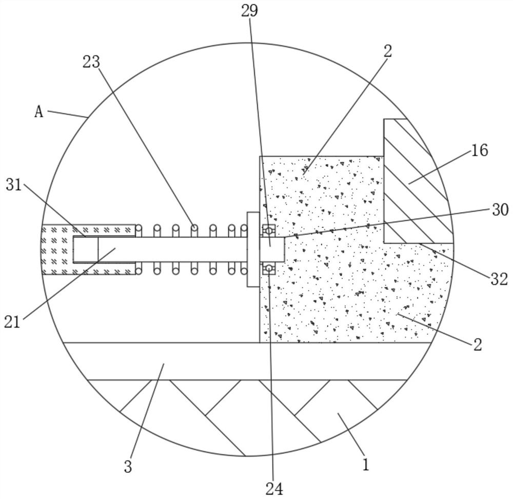
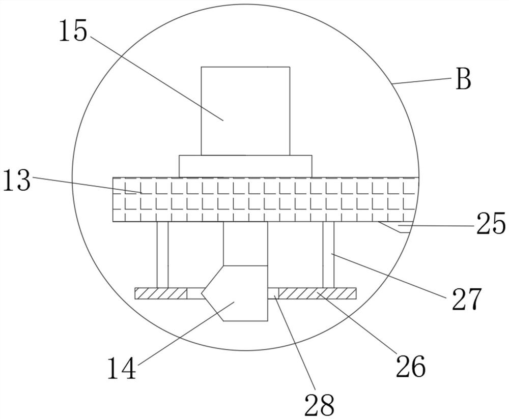
[0025] An automobile brake disc cutting precision control mechanism, comprising a base 1, an adjustment block 2 is installed on the upper end surface of the base 1, a chute 3 is opened transversely in the middle of the upper end surface of the base 1, and a left-right symmetrical groove is fixedly welded on the lower end surface of the adjustment block 2 A pair of slider...


PUM


Abstract

The invention relates to the technical field of brake disc machining equipment, in particular to an automobile brake disc cutting precision control mechanism which comprises a base. An adjusting blockis installed on the upper end face of the base, side plates are symmetrically arranged at the left side and the right side of the base, and upper supports are vertically welded to the front side andthe rear side of the upper end face of the base. The automobile brake disc cutting precision control mechanism has the beneficial effects that the purpose of adjusting the left-right position is achieved by arranging a pair of hydraulic cylinders which are symmetrical left and right and adjusting rods, coarse adjustment of the position is achieved through the hydraulic cylinders, fine adjustment of the left-right position is achieved by rotating extrusion of the adjusting rods through threads, and therefore repeated cutting of the single position is avoided, and the cutting efficiency and thecutting precision are greatly improved; through the arrangement of an annular plate, strip-shaped waste obtained after cutting is carried, and surface scratching caused by rotary cutting is avoided; and meanwhile, through cooperation of permanent magnet pieces and waste grooves, fine waste is adsorbed and recycled, secondary scratching caused by waste rolling is avoided, and the machining precision is greatly improved.

Description

technical field [0001] The invention relates to the technical field of brake disc processing equipment, in particular to an automobile brake disc cutting precision control mechanism. Background technique [0002] The brake disc, in simple terms, is a round disc that rotates when the car is moving. The brake caliper clamps the brake disc to generate braking force. When the brake is applied, it clamps the brake disc to slow down or stop the car. Disc brakes provide better braking and are easier to maintain than drum brakes. [0003] During the processing of the brake disc, it is necessary to cut the surface with a certain precision. However, the existing cutting device lacks the problem of precision control. Repetition of cutting will result in lower surface precision, and the falling of metal debris after cutting will easily cause scratches on the surface after cutting. [0004] Therefore, an automobile brake disc cutting precision control mechanism is provided to solve th...

Claims


Application Information

Patent Timeline
IPC IPC(8): B23Q15/00B23Q11/00
CPCB23Q11/0042B23Q15/00
Inventor 不公告发明人
Owner 胡美芳
Why Eureka
Eureka Blog
Learn More