Eureka AIR delivers breakthrough ideas for toughest innovation challenges, trusted by R&D personnel around the world.

Full-automatic optical fiber cutting machine

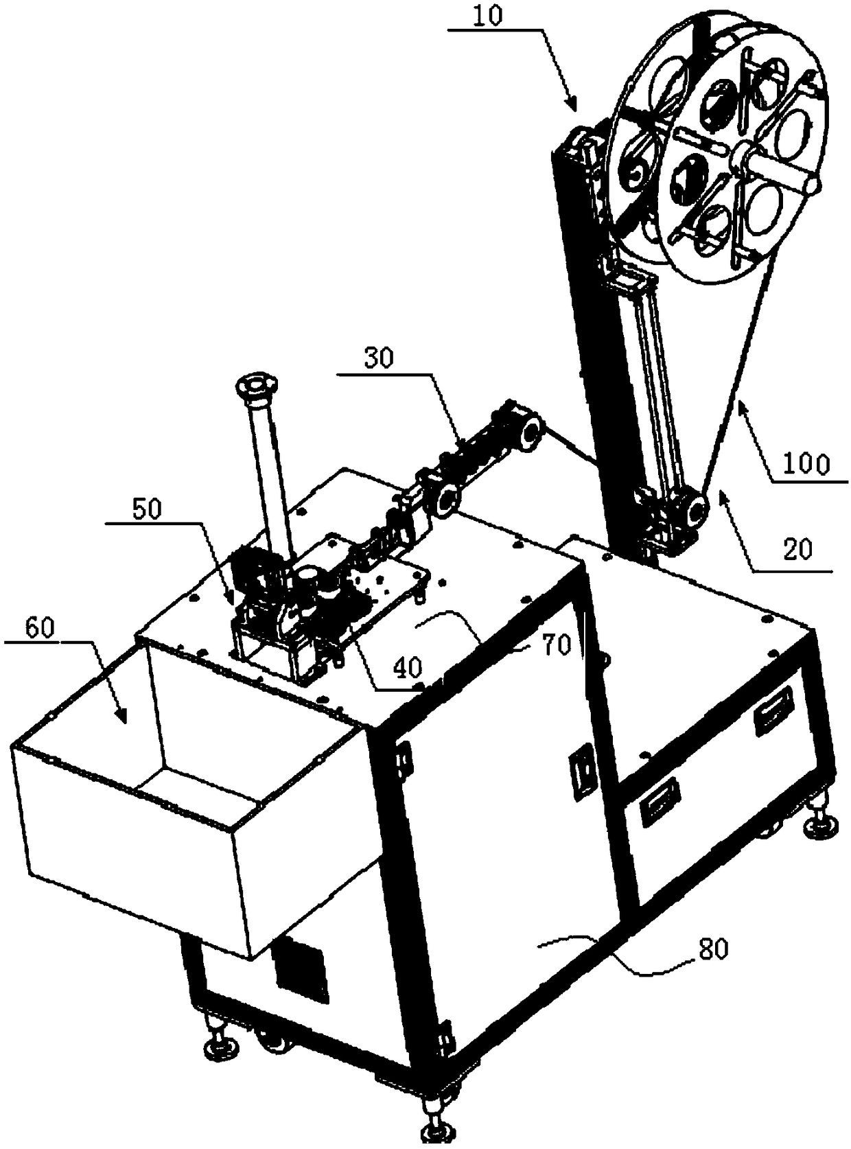
An optical fiber cutting machine, fully automated technology, applied in metal processing and other directions, can solve the problems of inability to effectively meet the simultaneous cutting of multiple optical fibers, operator injury, and low cutting precision, so as to improve cutting efficiency and The effect of cutting precision, reducing labor cost and improving efficiency

Pending Publication Date: 2018-11-06
昆山宇辰光通自动化科技有限公司
View PDF0 Cites 3 Cited by
  • Summary
  • Abstract
  • Description
  • Claims
  • Application Information

AI Technical Summary

Problems solved by technology

[0003] At present, in the production and processing of optical fibers, it is often necessary to cut and correct a single optical fiber or multiple optical fibers according to the needs of use, especially in the production of optical fibers and the operation of optical fibers. Cutting is an important part of optical fiber production and ensuring the quality of optical fiber. Due to the lack of professional equipment at present, the operator mainly relies on the operator to position the optical fiber by hand when cutting the optical fiber, and then use tools such as cutting scissors to cut the optical fiber. , the work efficiency is extremely low, and the cutting accuracy is relatively low, and it cannot effectively meet the needs of cutting multiple optical fibers at the same time. Therefore, in view of this situation, it is urgent to develop a new type of optical fiber cutting equipment to overcome the current shortcomings and meet the needs of actual use

Method used


Image

  • Full-automatic optical fiber cutting machine
  • Full-automatic optical fiber cutting machine
  • Full-automatic optical fiber cutting machine

Examples


Embodiment

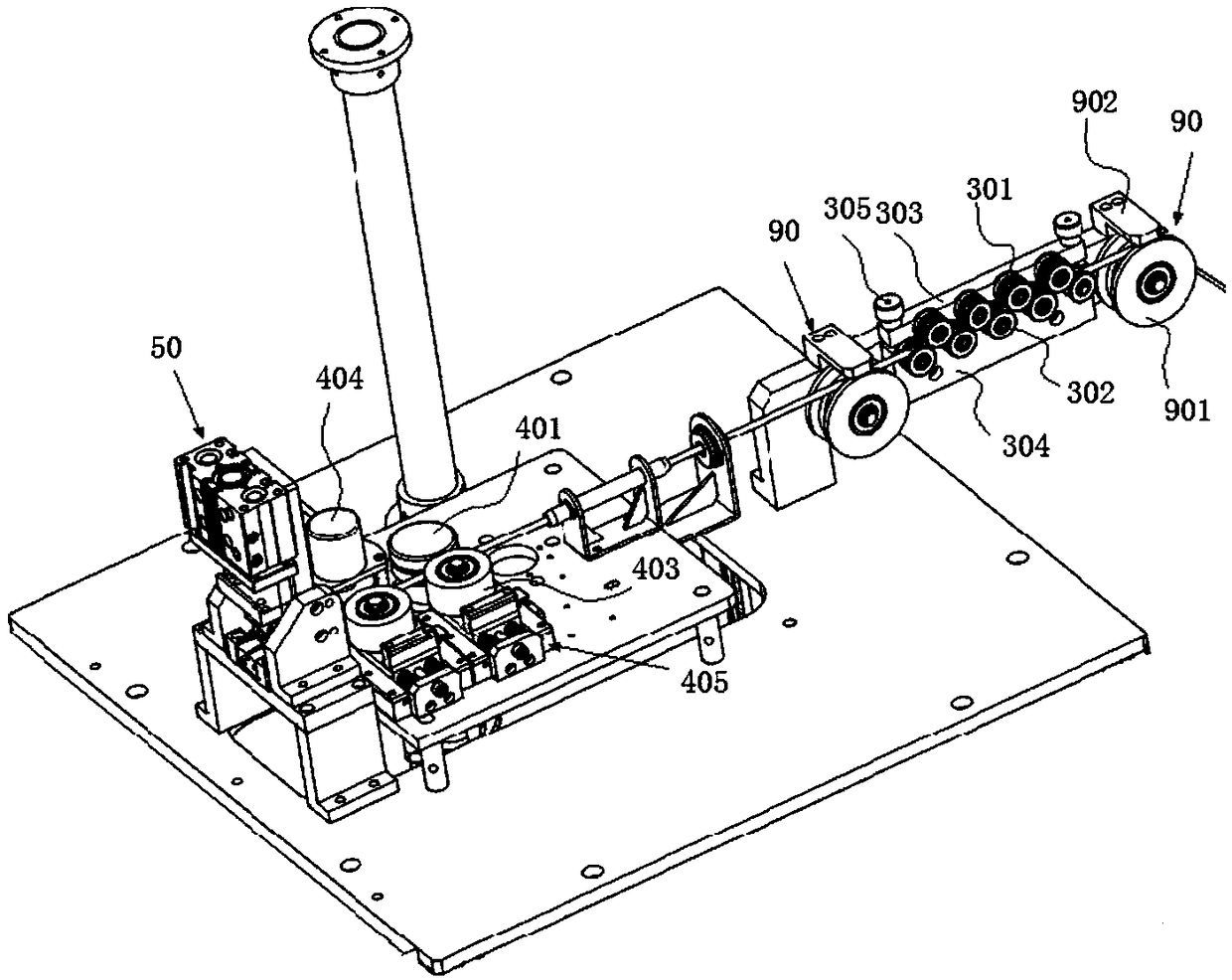
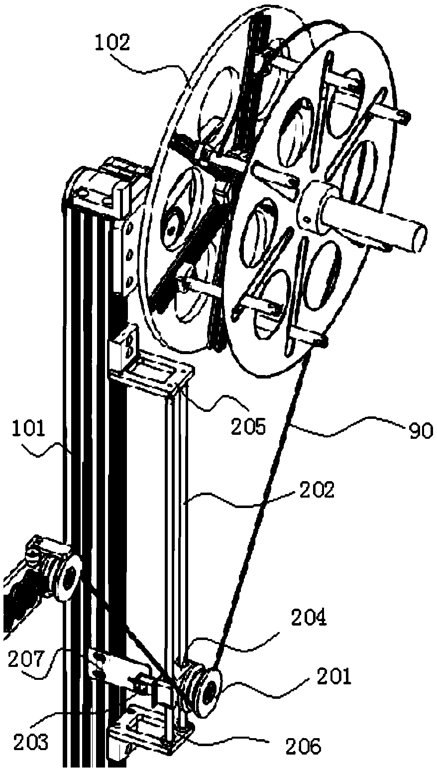
[0043] Embodiment: a kind of fully automatic optical fiber cutting machine, as Figure 1 to Figure 11 As shown, it includes a feeding device 10, a tensioning device 20, a straightening device 30, a traction device 40, a cutting device 50 and a receiving box 60 arranged in sequence according to the transmission direction of the optical fiber 100. The tightening device, the straightening device, the pulling device and the cutting device are all installed on the machine table 70, and the optical fiber is wound around the feeding device and bypasses the tensioning device and passes through the straightening device in turn. straight device and said traction device, then cut off by said cutting device and fall into the collection box;

[0044] Such as image 3 and Figure 4 As shown, the discharge device 10 includes a discharge rack 101, a discharge tray 102 and a first drive mechanism 103 that drives the rotation of the discharge tray, the discharge rack is installed on the machi...


PUM


Abstract

The invention discloses a full-automatic optical fiber cutting machine. The full-automatic optical fiber cutting machine comprises a feeding device, a tensioning device, a straightening device, a traction device, a cutting device and a material receiving box, wherein the feeding device, the tensioning device, the straightening device, the traction device, the cutting device and the material receiving box are arranged in sequence in the transmission direction of optical fiber. The optical fiber is wound around the feeding device, bypasses the tensioning device, and sequentially passes through the straightening device and the traction device, then is cut off by the cutting device and falls into the material receiving box. According to the full-automatic optical fiber cutting machine, a full-automatic operation mode is adopted, the optical fiber is cut into the optical fiber with required length after the optical fiber is straightened by the feeding device, the tensioning device, the straightening device, the traction device, the cutting device and the material receiving box in sequence, so that the cutting efficiency and the cutting precision of the optical fiber are improved, the cost is reduced, and the quality is guaranteed; and in the whole process, only coiled material wound with optical fiber needs to be placed manually, labor is greatly saved compared with manual cutting,and one person with more machines can be realized, efficiency is further improved, and labor costs are reduced. In addition, the full-automatic optical fiber cutting machine further has the characteristics of simple structure, high speed, stable quality, convenient adjustment and high universality.

Description

technical field [0001] The invention belongs to the technical field of automation equipment, and in particular relates to an automation equipment suitable for optical fiber cutting. Background technique [0002] As the carrier of information transmission, optical fiber is an important part of communication products and an important production material. [0003] At present, in the production and processing of optical fibers, it is often necessary to cut and correct a single optical fiber or multiple optical fibers according to the needs of use, especially in the production of optical fibers and the operation of optical fibers. Cutting is an important part of optical fiber production and ensuring the quality of optical fiber. Due to the lack of professional equipment at present, the operator mainly relies on the operator to position the optical fiber by hand when cutting the optical fiber, and then use tools such as cutting scissors to cut the optical fiber. , the work effici...

Claims


Application Information

Patent Timeline
IPC IPC(8): B26D1/08B26D7/06B26D7/14B26D7/27B26D7/28
CPCB26D1/08B26D7/06B26D7/14B26D7/27B26D7/28
Inventor 张英乾张博许士猛
Owner 昆山宇辰光通自动化科技有限公司
Why Eureka
Eureka Blog
Learn More