System and method for remotely monitoring automatic welding of mobile robot based on FPGA

An autonomous welding and remote monitoring technology, applied in welding equipment, laser welding equipment, metal processing equipment, etc., can solve the problems of only segmented welding, unable to complete welding seam at one time, unable to remotely display welding scene images, etc.

Active Publication Date: 2014-09-24
SOUTH CHINA UNIV OF TECH
View PDF6 Cites 40 Cited by
  • Summary
  • Abstract
  • Description
  • Claims
  • Application Information

AI Technical Summary

Problems solved by technology

[0003] ①The welding robot is too bulky to move flexibly and can only work in a fixed location
The welding robot needs a large working space when working, and it is difficult to work in a small space;
[0004] ②The fixed welding robot has a limited stroke. For the long welds of large components, such as the welds of the seams of ships, it cannot weld all the welds at one time, and can only weld in sections, which affects the welding quality and efficiency;
[0005] ③Existing welding robots weld according to the pre-programmed or taught fixed trajectory. However, the position of workpiece processing and assembly will be different each time. Deviation, and if each workpiece is taught, the workload is very large;
[0006] ④Sometimes for special welds, the welding robot cannot be adjusted in real time, and the robot needs to be manually operated. However, the existing robots cannot remotely display the image of the welding scene during work. Workers must observe the weld at close range with the naked eye, which is very inconvenient. Moreover, the strong arc light will also cause harm to the human body.
[0007] ⑤ The cost of robots is too high, the price of a robot is at least more than 100,000 yuan, which increases the cost of manufacturing

Method used


Image

  • System and method for remotely monitoring automatic welding of mobile robot based on FPGA
  • System and method for remotely monitoring automatic welding of mobile robot based on FPGA
  • System and method for remotely monitoring automatic welding of mobile robot based on FPGA

Examples


Embodiment Construction

[0032] The present invention will be further described in detail below in conjunction with the embodiments and accompanying drawings.

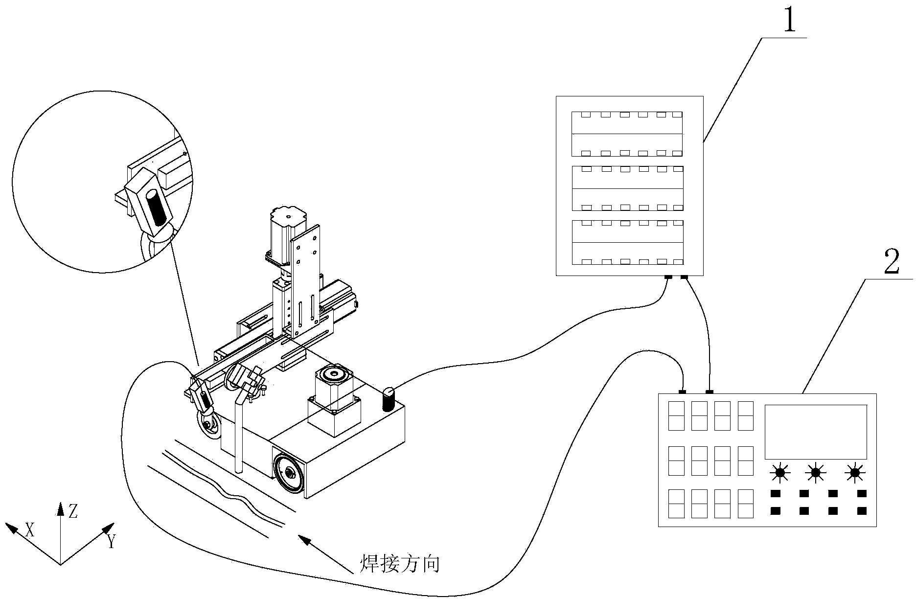
[0033] Such as figure 1 As shown, the FPGA-based remote monitoring mobile autonomous welding robot system structure includes:

[0034] The system includes: a welding robot, a welding seam position detection sensor system, a control cabinet 1 and an FPGA-based remote operation controller 2;

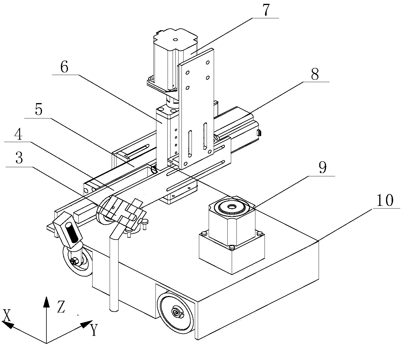
[0035] The welding robot is used to hold the welding torch and carry the sensor system, and drive the movement of the welding torch in the X, Y and Z three-dimensional directions;

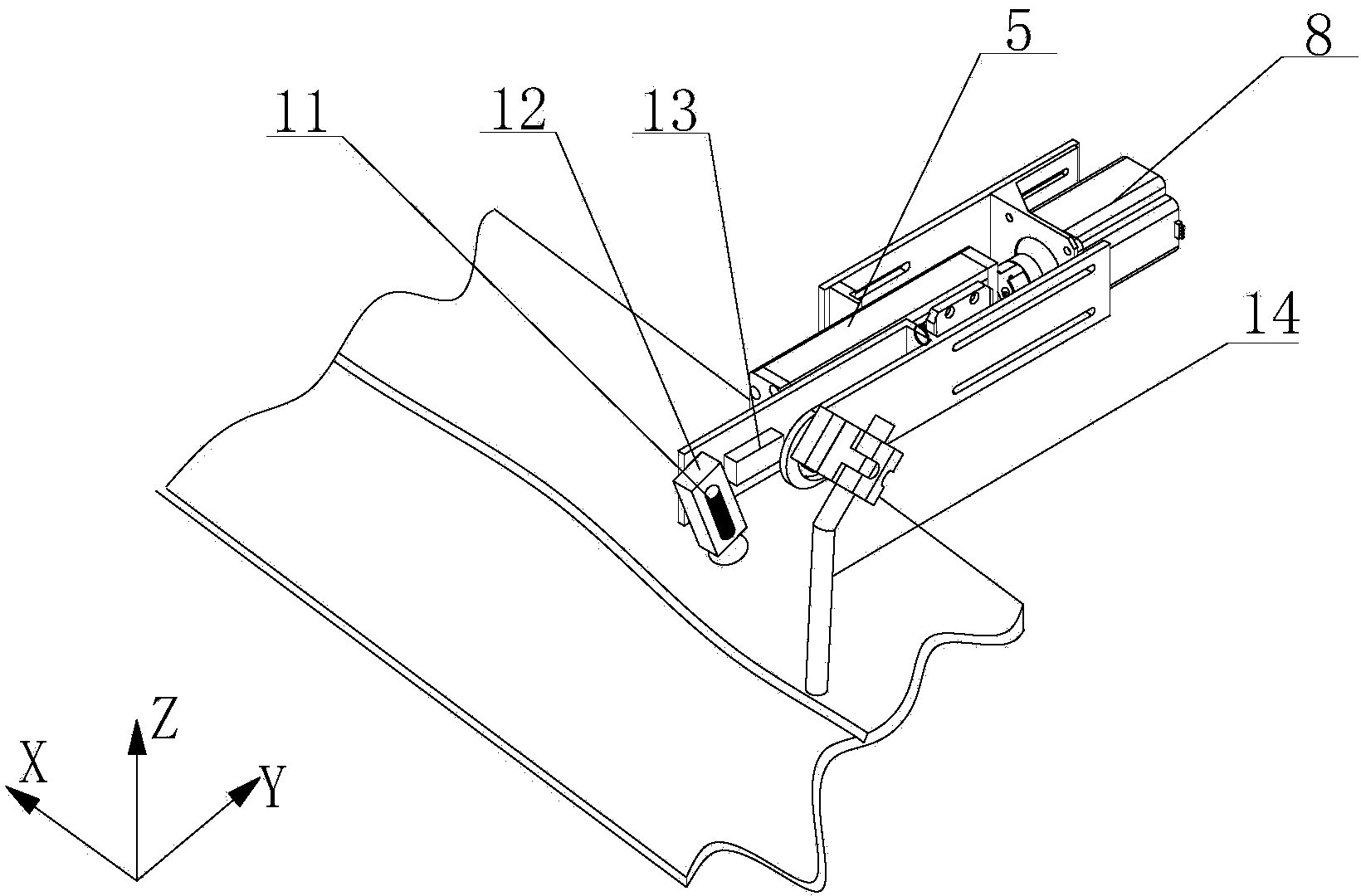
[0036] The welding seam position detection sensor system sends the position information in the Z direction, the broken line laser image and the welding scene video to the remote operation controller 2;

[0037] Remotely operate the controller, convert the position information in the Z direction into the distance value between the welding torch and the weld seam in the Z direc...


PUM


Abstract

The invention discloses a system for remotely monitoring automatic welding of a mobile robot based on an FPGA. The system comprises a welding robot, a welding seam position detection sensor system, a control cabinet and a remote operation controller based on the FPGA. The welding robot is used for clamping a welding gun, carrying the sensor system and driving the welding gun to move in the X, Y and Z directions. The welding seam position detection sensor system is used for sending position signals in the Z direction, broken line laser images and welding scene videos to the remote operation controller. The remote operation controller is used for setting welding parameter values, displaying remote welding scene videos, working out the needed moving distances of the welding gun in the Y direction and the Z direction, sending pulse and direction signals to the control cabinet and automatically adjusting the position of the welding gun in the Y direction and the Z direction. The control cabinet is used for controlling a stepping motor to rotate so as to adjust the positions of the welding gun in the Y direction and the Z direction.

Description

technical field [0001] The patent of the present invention belongs to the field of welding equipment, and in particular relates to an FPGA-based remote monitoring mobile robot autonomous welding system and method. Background technique [0002] With the continuous development of welding technology and the lack of welding technicians, welding robots are more and more widely used, but the existing fixed six-degree-of-freedom welding robots generally have the following shortcomings and deficiencies: [0003] ①The welding robot is too bulky to move flexibly and can only work in a fixed location. The welding robot needs a large working space when working, and it is difficult to work in a small space; [0004] ②The fixed welding robot has a limited stroke. For the long welds of large components, such as the welds of the seams of ships, it cannot weld all the welds at one time, and can only weld in sections, which affects the welding quality and efficiency; [0005] ③Existing weld...

Claims


Application Information

Patent Timeline
Patent Type & Authority Applications(China)
IPC IPC(8): B23K26/02B23K26/70
CPCB23K26/02B23K26/702
Inventor 石永华俞国庆龚成石弟军梁斌
Owner SOUTH CHINA UNIV OF TECH
Why Eureka
Try Eureka