Cam-type pedal lock braking mechanism

A cam-type, pedal-operated technology, which is applied to metal processing machinery parts, driving devices, metal processing equipment, etc., can solve the problem of large structure of the spring return part, and achieve the effects of fast braking speed, low cost and convenient adjustment

Active Publication Date: 2014-09-24
SHANDONG LUNAN MACHINE TOOL
View PDF5 Cites 1 Cited by
  • Summary
  • Abstract
  • Description
  • Claims
  • Application Information

AI Technical Summary

Problems solved by technology

[0003] The purpose of the present invention is to provide a cam-type pedal brake mechanism, which solves the common defects of conventional friction brakes such as the large structure of the spring return part.

Method used


Image

  • Cam-type pedal lock braking mechanism
  • Cam-type pedal lock braking mechanism
  • Cam-type pedal lock braking mechanism

Examples


Embodiment Construction

[0015] The present invention will be further described below in conjunction with accompanying drawing and specific embodiment:

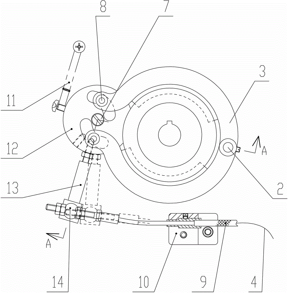
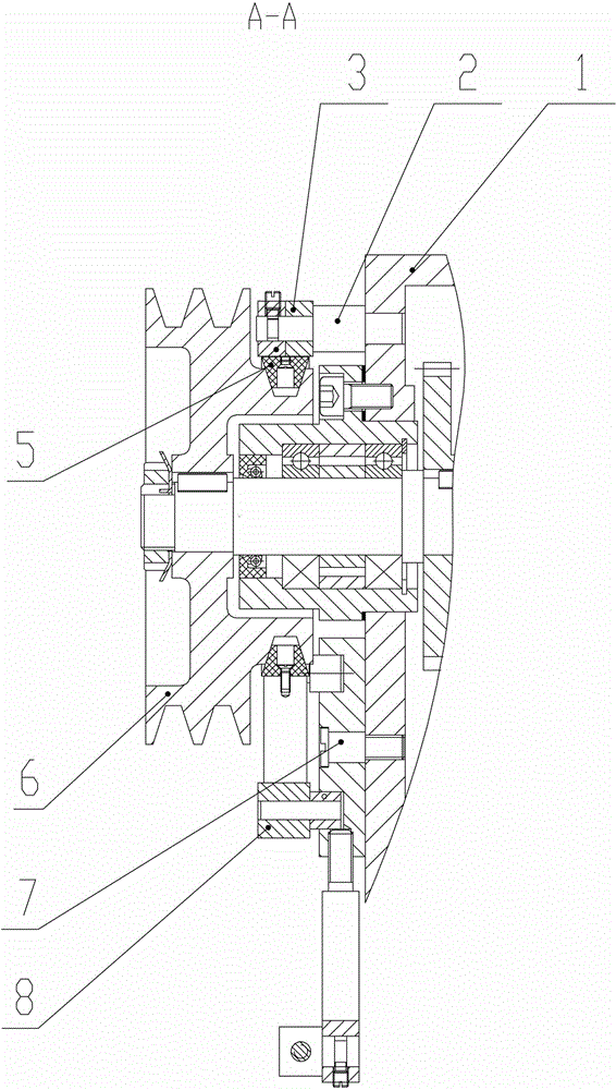
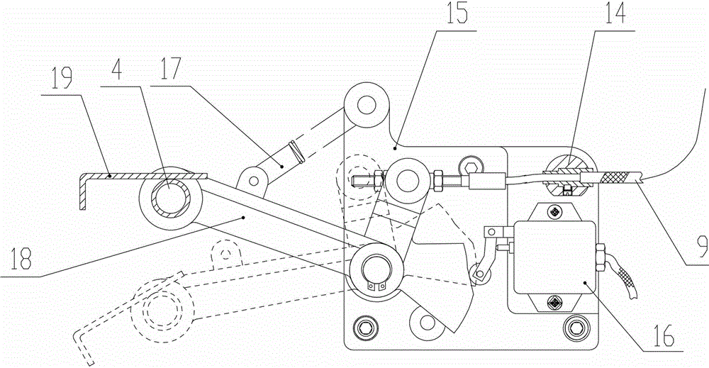
[0016] A cam-type pedal brake mechanism, comprising a pedal part, a brake cable 9, and a brake brake part, characterized in that the pedal part includes a support plate 15, a pedal 19, and a brake limit block 14. Cam lever 18 and travel switch 16, the brake brake part includes brake runner 12, brake block 3 and brake pad, brake cable 9 and cable support seat 10;

[0017] The support plate 15 is vertically fixed on the side of the front leg of the lathe, the cam end of the cam lever 18 is arranged on the support plate 15 through a pin shaft, and the middle position of the cam lever 18 is provided with a pedal extension spring 17, and the pedal extension spring 17 The other end is connected on the support plate 15, the travel switch 16 is fixed on the support plate 15, the contact of the travel switch 16 is located within the range of the cam rotation ...


PUM


Abstract

The invention relates to a braking mechanism, in particular to a cam-type pedal lock braking mechanism. According to the adopted technical scheme, the cam-type pedal lock braking mechanism comprises a pedal part, a braking connecting line and a braking part, and is characterized in that the pedal part comprises a support plate, a pedal plate, a braking line limiting block, a limiting brake rod, a cam rod and a travel switch; the braking part comprises a brake runner, a brake cable, a brake block and a brake pad. The cam-type pedal lock braking mechanism has the advantages that the friction force between the brake pad and a moving part is used for braking, and rotation or rotation trend is stopped by means of mutual friction between a non-rotating element and a rotating element. The cam-type pedal lock braking mechanism has the characteristics of flexibility in braking, simple structure, convenience in adjustment, low cost, high suitability and the like, and a belt axle in a headstock of a machine tool can be used for braking. The cam-type pedal lock braking mechanism has the advantages of compact structure, flexibility in action, convenience in adjustment, great braking force, high braking speed, adjustable braking time, automatic compensation after wear of the brake pad, and the like.

Description

technical field [0001] The invention relates to a brake mechanism, in particular to a cam type pedal lock mechanism. Background technique [0002] Brakes, commonly known as brakes, are devices that stop, decelerate or maintain stop assembly of moving parts in machinery, and are mechanical parts that stop or decelerate moving parts in machinery. The currently used friction brakes generally have defects such as a large structure of the spring return part. Contents of the invention [0003] The purpose of the present invention is to provide a cam-type pedal brake mechanism, which solves the common defects of conventional friction brakes such as the large structure of the spring return part. [0004] To achieve the above object, the technical solution adopted in the present invention is: [0005] A cam type pedal holding brake mechanism, comprising a pedal part, a brake cable, and a brake brake part, characterized in that the pedal part includes a support plate, a pedal, a b...

Claims


Application Information

Patent Timeline
Patent Type & Authority Applications(China)
IPC IPC(8): B23Q5/20
CPCB23Q5/20
Inventor 刘斌于艳东李天昊汪玉伟神菁岐
Owner SHANDONG LUNAN MACHINE TOOL
Why Eureka
Try Eureka