An auger support device

A technology of auger and support frame, which is applied in the direction of packaging and pivot connection, etc., which can solve the problems of affecting production efficiency, heavy workload and difficulty, and affecting the service life of the sand conveying auger

Inactive Publication Date: 2016-08-24
NORTHERN HEAVY IND GRP CO LTD
View PDF8 Cites 0 Cited by
  • Summary
  • Abstract
  • Description
  • Claims
  • Application Information

AI Technical Summary

Problems solved by technology

The current support structure of the sand conveying auger has high processing requirements. Even if the processing requirements can be met, the assembly requirements are also very high. The workload and difficulty of on-site assembly are very large, which affects production efficiency; , bringing additional force to the pin shaft, seriously affecting the service life of the sand conveying auger

Method used


Image

  • An auger support device
  • An auger support device
  • An auger support device

Examples


Embodiment Construction

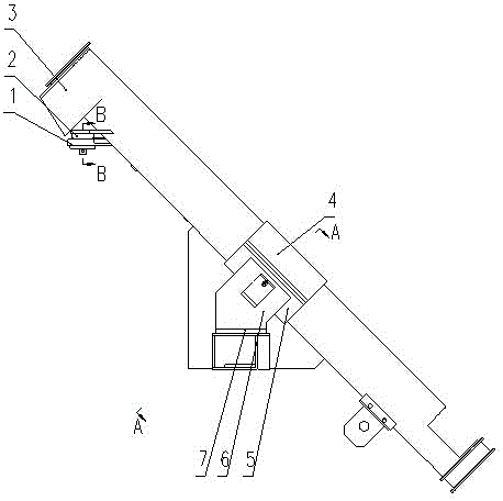
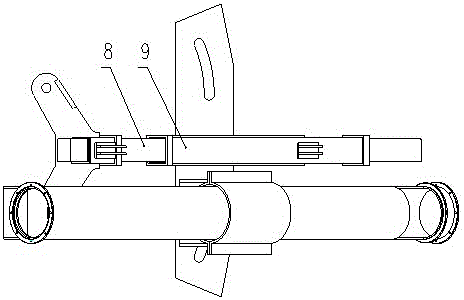
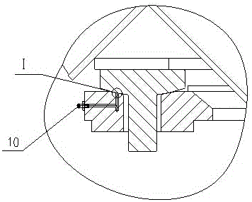
[0015] Referring to the accompanying drawings, an auger support device includes a concave spherical support plate 1, a convex spherical pin shaft 2, an auger shell 3, an upper guide sleeve 4, a lower guide sleeve 5, a support frame body 6, a backing plate 7, and a movable rectangular Tube 8, fixed rectangular tube 9, oil cup 10, lock nut 11, mandrel 12, nylon roller 13, U-shaped bracket 14, convex spherical surface pin 2 welded on auger shell 3, concave spherical surface supporting plate 1 welded On the movable rectangular tube 8, the convex spherical surface pin shaft 2 is inserted into the pin hole of the concave spherical surface supporting plate 1, the movable rectangular tube 8 is set in the fixed rectangular tube 9, and the upper guide sleeve 4 and the lower guide sleeve 5 are bolted together. Together, the lower guide sleeve 5 is welded to the support frame body 6, and the backing plate 7 is placed under the support frame body 6; the convex spherical surface pin shaft 2 ...


PUM


Abstract

An auger support device used in the oil field industry, including a concave spherical support plate, a convex spherical pin shaft, an auger shell, an upper guide sleeve, a lower guide sleeve, a support frame body, a backing plate, a movable rectangular tube, and a fixed rectangular tube , oil cup, lock nut, mandrel, nylon roller, U-shaped bracket, waist hole, the convex spherical pin is welded on the auger shell, the concave spherical supporting plate is welded on the movable rectangular tube, and the convex spherical pin is inserted into the In the pin hole of the concave spherical support plate, the movable rectangular tube is set in the fixed rectangular tube, the upper guide sleeve and the lower guide sleeve are bolted together, the lower guide sleeve is welded to the support frame body, and the backing plate is placed under the support frame body; The spherical pin shaft is matched with the concave spherical supporting plate, and the oil cup is installed on the concave spherical supporting plate; the U-shaped bracket is welded on the supporting frame body. The spherical pair of the device rotates around the center of the sphere to provide a certain small displacement to compensate for errors caused by processing or assembly; the spherical pair rotates to provide a small displacement to avoid additional force at the pin shaft and prolong the service life of the sand conveying auger.

Description

technical field [0001] The invention relates to an auger support device for a sand mixing vehicle in the oil field industry. Background technique [0002] The sand mixing vehicle is an important supporting equipment in the oil field, which is responsible for providing fracturing fluid to the fracturing vehicle. There is a sand conveying auger at the tail of the sand mixing vehicle, which is responsible for providing proppant to the sand mixing vehicle. The auger and the ground have an inclination angle of 45 degrees. During on-site operation, it is necessary to drop the sand auger to the ground, and the two sand augers should be separated to facilitate on-site operation. The current support structure of the sand conveying auger has high processing requirements. Even if the processing requirements can be met, the assembly requirements are also very high. The workload and difficulty of on-site assembly are very large, which affects production efficiency; , bringing additiona...

Claims


Application Information

Patent Timeline
Patent Type & Authority Patents(China)
IPC IPC(8): B65G33/24B65G33/26F16C11/06
Inventor 霍光赵绪平李宣周伟常亮刘晓旭
Owner NORTHERN HEAVY IND GRP CO LTD
Why Eureka
Try Eureka