

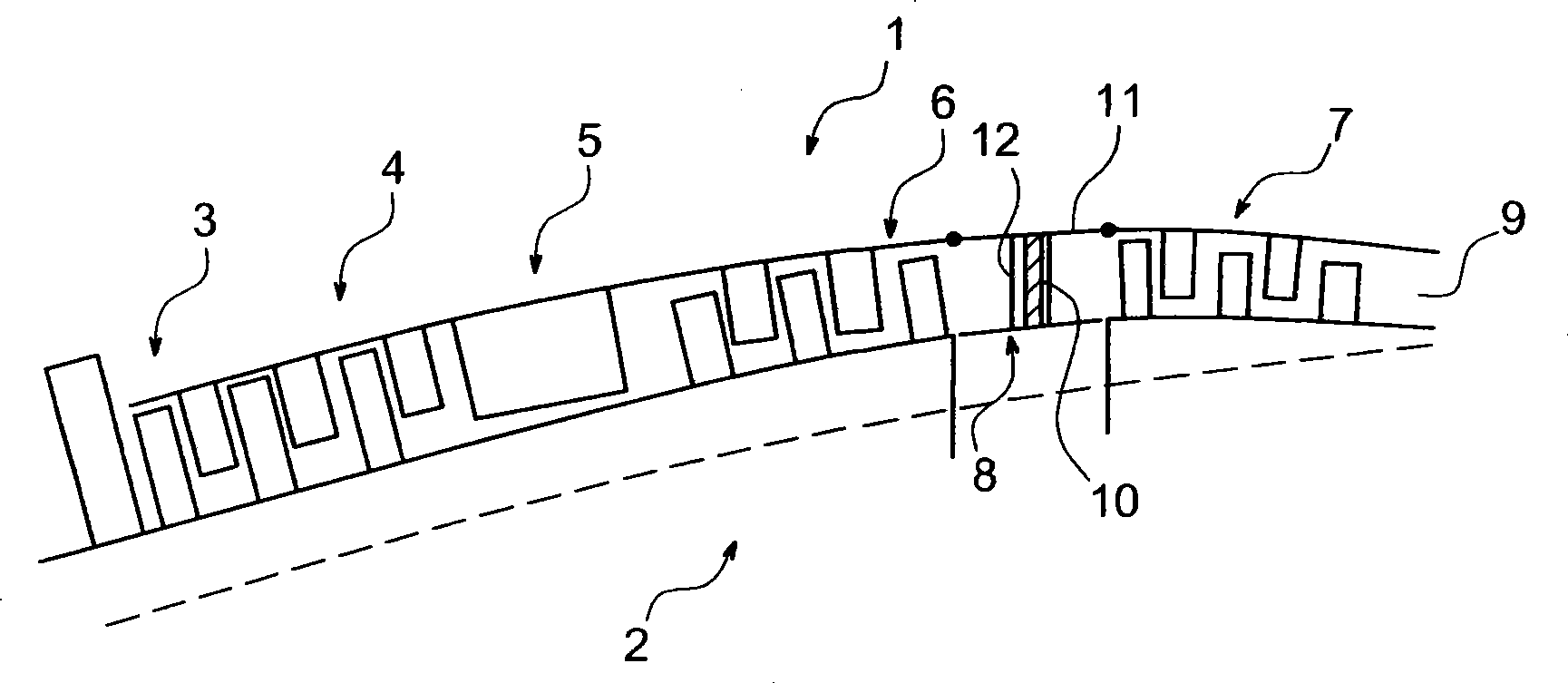
Connection of radial struts to a circular casing by pins and spacers
A technology of radial arm and sleeve, which is applied in the field of connection between the radial arm and the circular sleeve through the shaft and spacer, which can solve the problems of oversized design and inability to disassemble the radial arm, and achieve simple components and low weight. Lightweight, ensures precise positioning effect
- Summary
- Abstract
- Description
- Claims
- Application Information
AI Technical Summary
Problems solved by technology
Method used
Image

Examples
Embodiment Construction
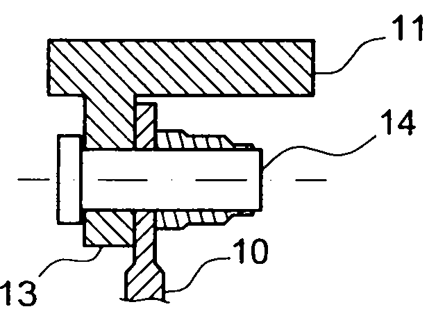
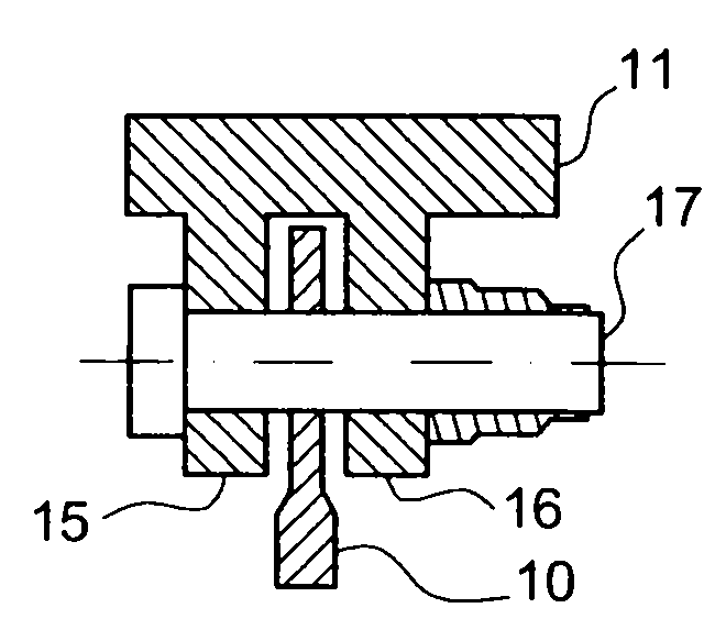
[0020] The end of the radial arm 10 is provided with two parallel perforations 20 at its end, which are of the smallest size and placed on opposite sides ( Figure 5 with Figure 8 ). Axis 21 ( Figure 5 with Image 6 ) engages with and passes through the perforation 20. These shafts comprise a central part 22 with the same cross-section (preferably circular) as the perforations 20 and placed inside these perforations, and two lateral parts 23 protruding outwards from the radial arms 10, each There is a shaft through hole 24 on each part. The lateral portion 23 has a flat surface 25 on it. The structure further includes spacers 26 ( Figure 5 with Figure 7 ), on which a pair of spacer perforations 27 are arranged parallel to each other.
[0021] Outer sleeve 11 is provided with protuberance 28 (boss) ( Figure 5 with Figure 9 ), combined with each connecting member, the surface of which is planar or cylindrical, cylindrical so that its axis is the same as that of t...
PUM
 Abstract
Description
Claims
Application Information