Sliding wheel mechanism for lifting machine

A technology of hoisting machinery and pulleys, which is applied in the field of a device for changing the magnification of the pulley mechanism of large-scale hoisting machinery during work. The effect of convenient and fast operation, improved work efficiency, light and fast magnification conversion

Active Publication Date: 2014-09-24
KERUN ELECTRO MECHANICAL ENG
View PDF11 Cites 0 Cited by
  • Summary
  • Abstract
  • Description
  • Claims
  • Application Information

AI Technical Summary

Problems solved by technology

[0003] The easiest way to change the magnification in the existing technology is to manually re-thread the rope, but at an altitude of more than 100 meters, it is difficult or even impossible to manually re-thread the rope
Moreover, the hoisting of large parts in the project is not in the same period, and the large and small parts are often interspersed. The magnification needs to be changed frequently, and it is not advisable to rely solely on manual stringing
In addition, the magnification of large-scale hoisting machinery is very large, so its rope winding system is also very complicated. For such a complicated rope winding system, it is even more difficult to easily and quickly change the magnification. The problem of changing magnification in

Method used


Image

  • Sliding wheel mechanism for lifting machine
  • Sliding wheel mechanism for lifting machine
  • Sliding wheel mechanism for lifting machine

Examples


Embodiment Construction

[0023] The present invention will be further described below in conjunction with embodiment (accompanying drawing):

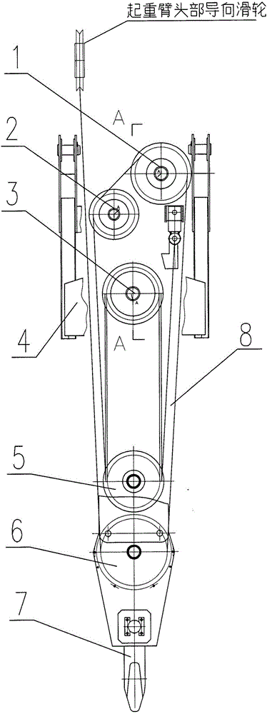
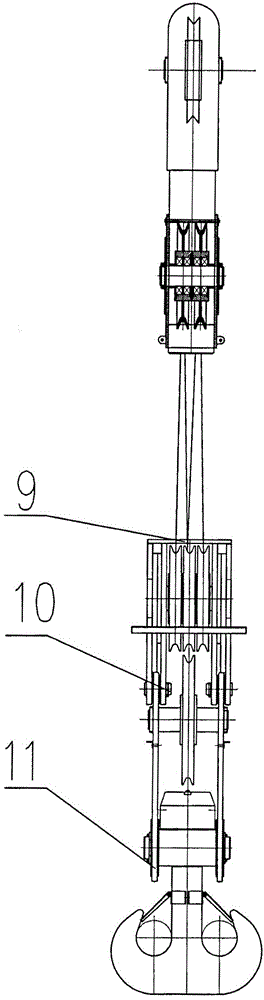
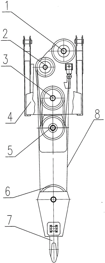
[0024] Such as figure 1 , 2 As shown, the pulley mechanism of the hoisting machine of the present invention includes and is installed on the fixed pulley block of the boom head, the first movable pulley block 5 installed on the first movable pulley bracket 9, the installation The second movable pulley block 6 and the suspension hook group 7 on the second movable pulley support 11; the described fixed pulley block is composed of two left and right fixed pulleys 1, 2 and a bottom fixed pulley block 3 arranged on the fixed pulley support top, and the first A movable pulley block is hoisted below the fixed pulley block by the traction wire rope 8, and the second movable pulley bracket 11 equipped with the second movable pulley block and the hook group 7 is combined with the lower end of the first movable pulley bracket through a detachable pin shaft 10; The axes ...


PUM


Abstract

The invention discloses a sliding wheel mechanism for a lifting machine. The sliding wheel mechanism is characterized by comprising a fixed sliding wheel group mounted at the head part of a lifting beam through a fixed sliding wheel bracket and corresponding connecting pieces, a first movable sliding wheel group mounted on a first movable sliding wheel bracket, a second movable sliding wheel group and lifting hooks mounted on a second sliding wheel bracket; the fixed sliding wheel group comprises a left fixed sliding wheel and a right fixed sliding wheel arranged at the upper part of the fixed sliding wheel bracket, as well as a fixed sliding wheel group arranged at the lower part of the fixed sliding wheel bracket; the first movable sliding wheel group is mounted under the fixed sliding wheel group in a lifting manner through tractive steel wire ropes; the second movable sliding wheel bracket mounted the second movable sliding wheel group and the lifting hooks is combined with the lower end of the first movable sliding wheel bracket through a detachable connecting piece.

Description

technical field [0001] The invention relates to a pulley mechanism of a hoisting machine, in particular to a device for changing the magnification of the pulley mechanism of a large hoisting machine during work. Background technique [0002] In the design of the crane, it is very important to determine the ratio of the pulley block reasonably. Generally, it is hoped to achieve low speed for heavy load and high speed for light load. According to this design principle, a large magnification is generally used when lifting a large lifting weight, which can avoid the use of too thick wire ropes and reduce the lifting speed correspondingly. But when the same mechanism lifts medium and small lifting weights, if the pulley ratio is not changed and the lifting speed is still very low, the effective power of this mechanism cannot be brought into play, and the service efficiency is too low. At present, the maximum lifting capacity of large-scale hoisting machinery can reach hundreds o...

Claims


Application Information

Patent Timeline
Patent Type & Authority Applications(China)
IPC IPC(8): B66D3/06B66D3/08
Inventor 胡水根李太周胡斌江萍郭志康
Owner KERUN ELECTRO MECHANICAL ENG
Why Eureka
Try Eureka