
Uniform motion pipeline pump

A technology for pipeline pumps and pump casings, applied in the direction of pumps, pump components, variable capacity pump components, etc., can solve problems such as inability to guarantee product quality, and achieve the effects of wide application range, small pressure pulsation, and simple structure

Active Publication Date: 2014-09-24
楚天源创生物技术(长沙)有限公司
View PDF6 Cites 5 Cited by
  • Summary
  • Abstract
  • Description
  • Claims
  • Application Information

AI Technical Summary

Problems solved by technology

In chemical, food, pharmaceutical, bioengineering and other fields, there are high requirements for flow pulsation and flow accuracy, but traditional pumps cannot fully meet the requirements, and product quality cannot be guaranteed during use.

Method used


Image

  • Uniform motion pipeline pump
  • Uniform motion pipeline pump
  • Uniform motion pipeline pump

Examples


Embodiment Construction

[0025] The following examples are further explanations and illustrations of the present invention, and do not constitute any limitation to the present invention.

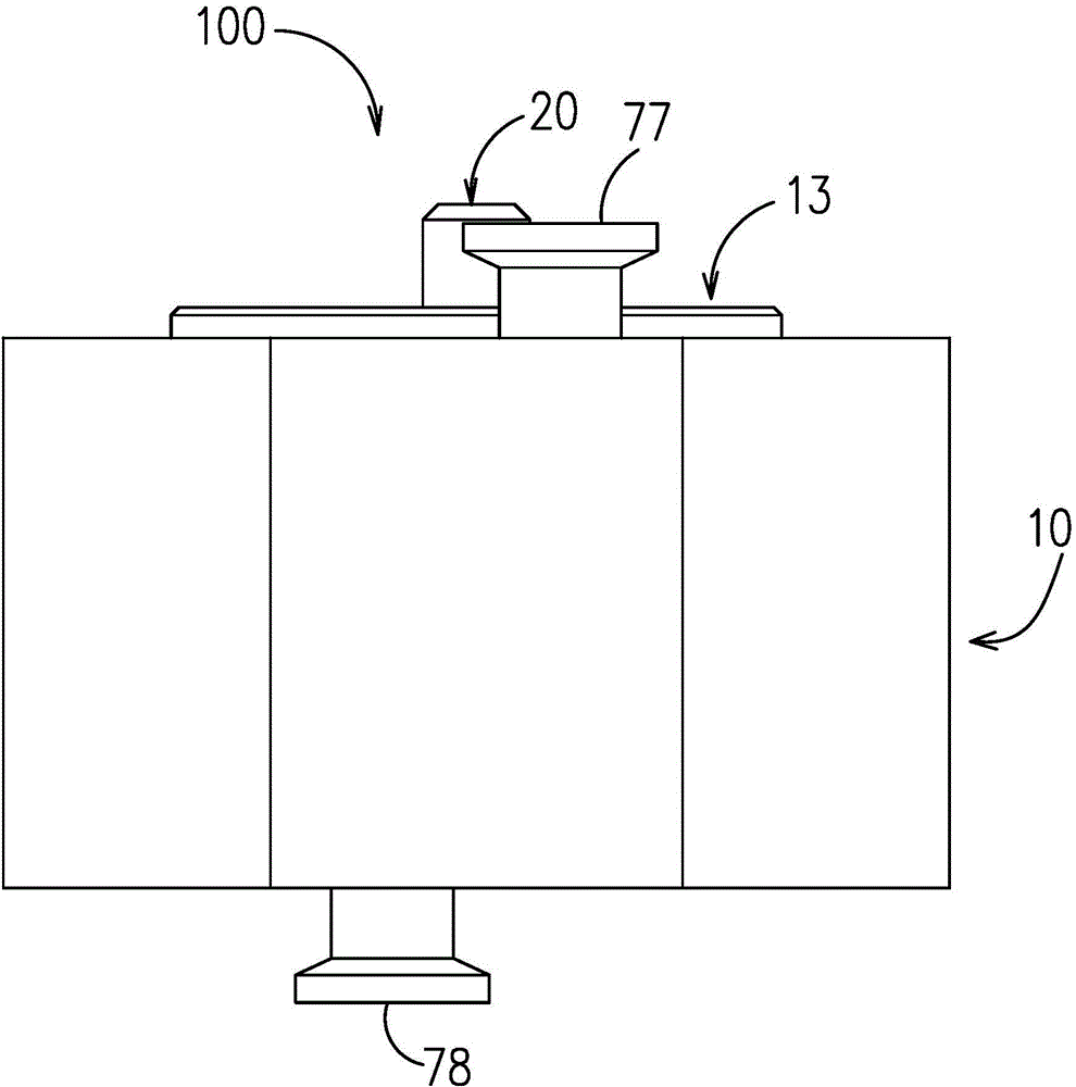
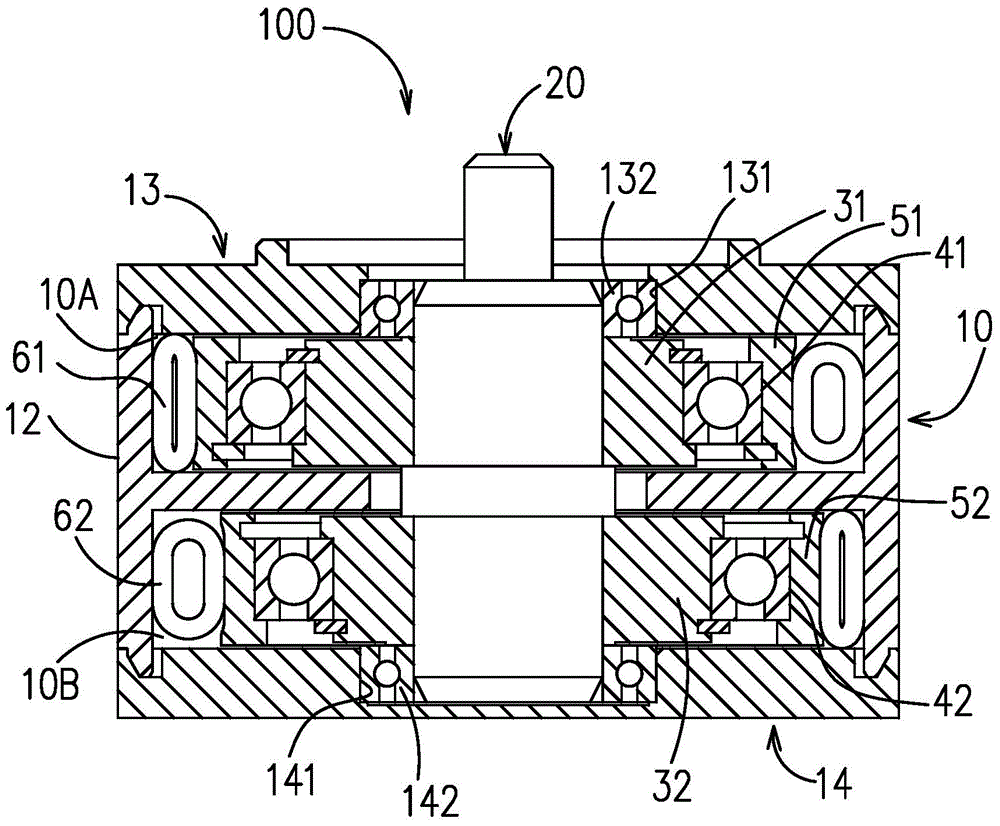
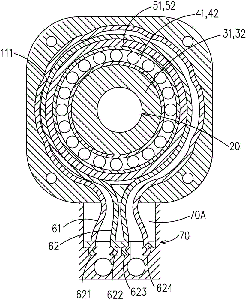
[0026] refer to Figure 1 ~ Figure 3 , The uniform motion pipeline pump 100 of the present invention includes a pump casing 10 , a central shaft 20 , eccentric wheels 31 , 32 , pressure wheels 51 , 52 , liquid pipes 61 , 62 and a filter joint 70 .

[0027] Such as Figure 1 ~ Figure 3 , the uniform motion pipeline pump 100 includes a steel pump casing 10. In this embodiment, the pump casing 10 is composed of a pump casing main body 12, a first end cover 13, and a second end cover 14. The structure of the first end cap 13 is as follows: Figure 10 As shown, there is a bearing hole 131 in its center, and a bearing 132 for supporting the central shaft 20 is fixed in the bearing hole 131, and a U-shaped groove 133 is arranged on the end surface of the opposite side of the pump casing main body 12, and O shaped seals,...


PUM


Abstract

The invention discloses a uniform motion pipeline pump. The uniform motion pipeline pump comprises a pump casing; a cylindrical inner cavity is formed in the pump casing; a plurality of convex curved surfaces are arranged on the inner wall of the cylindrical inner cavity; a central shaft is arranged in the inner cavity of the pump casing; two eccentric wheels are arranged on the central shaft; a bearing is fixed outside each eccentric wheel; a pressing wheel is fixed on each bearing; two gaps are formed between the two pressing wheels and the inner cavity wall of the pump casing; liquid passing pipes which can be deformed elastically are arranged in the two gaps; a filtering joint is arranged on the pump casing, and is provided with a liquid inlet hole and a liquid outlet hole. The liquid passing pipes are compressed completely by pressing wheels at the minimum gaps, and the liquid cannot pass; when the central shaft is driven by the motor to rotate, the pressing wheels press the liquid in the pipes through the liquid passing pipes; pressure difference is formed on the two sides of the minimum gaps; the liquid is inhaled on the low pressure side; the liquid is exhausted on the high pressure side; pulsating flow rates output by the two liquid passing pipes is combined into a flow rate with a relatively uniform pulsating range at the liquid inlet hole and the liquid outlet hole of the filtering joint.

Description

【Technical field】 [0001] The invention relates to a liquid pump, in particular to a uniform pipeline pump which can reduce the pulsation of flow and pressure to realize approximately constant flow. 【Background technique】 [0002] A pump is a machine that transports or pressurizes a liquid. It transfers the mechanical energy of the prime mover or other external energy to the liquid to increase the energy of the liquid. Pumps are widely used to transport liquids such as water, oil, acid and alkali liquids, emulsions, suspoemulsions and liquid metals, as well as liquids, gas mixtures and liquids containing suspended solids. Traditional pumps include centrifugal pumps, diaphragm pumps, piston pumps, peristaltic pumps, etc. In chemical, food, pharmaceutical, bioengineering and other fields, there are high requirements for flow pulsation and flow accuracy, but traditional pumps cannot fully meet the requirements, and product quality cannot be guaranteed during use. Therefore, i...

Claims


Application Information

Patent Timeline
Patent Type & Authority Applications(China)
IPC IPC(8): F04B43/09F04B53/16
Inventor 肖立峰
Owner 楚天源创生物技术(长沙)有限公司
Learn More