Onboard panorama monitoring system of unmanned aerial vehicle

A panoramic monitoring and unmanned aerial vehicle technology, which is applied in the field of aerial remote sensing, can solve the problems of limited disaster rescue evaluation and emergency control processing, inability to obtain first-hand information in time, and poor interconnection of components, so as to improve monitoring efficiency. , Take-off and landing takes up a small area and achieves the effect of rapid positioning

Inactive Publication Date: 2014-09-24
BEIJING RES INST OF SPATIAL MECHANICAL & ELECTRICAL TECH
View PDF6 Cites 17 Cited by
  • Summary
  • Abstract
  • Description
  • Claims
  • Application Information

AI Technical Summary

Problems solved by technology

[0003] On the other hand, with the explosive population growth, various natural disasters and emergencies (such as East Turkistan, Tibetan independence, etc.) occur frequently. If the progress of the situation cannot be kept abreast of, it will seriously limit the rescue assessment of disasters and the emergency response to emergencies. Therefore, there is an urgent need for real-time dynamic monitoring equipment with convenient deployment, high mobility, and high real-time information
[0004] At present, the existing products are all simple combinations of drones, remote sensors and transmission equipment. After the image information is transmitted back, further processing is required, and the first-hand information cannot be obtained in time. The interconnection of each component is poor. It requires the simultaneous operation of multiple professionals, and has high professional requirements for operators, and the product is poor in systematization, single in function, and low in reliability.

Method used


Image

  • Onboard panorama monitoring system of unmanned aerial vehicle
  • Onboard panorama monitoring system of unmanned aerial vehicle
  • Onboard panorama monitoring system of unmanned aerial vehicle

Examples


Embodiment Construction

[0019] The present invention will be described in detail below in conjunction with the accompanying drawings and embodiments.

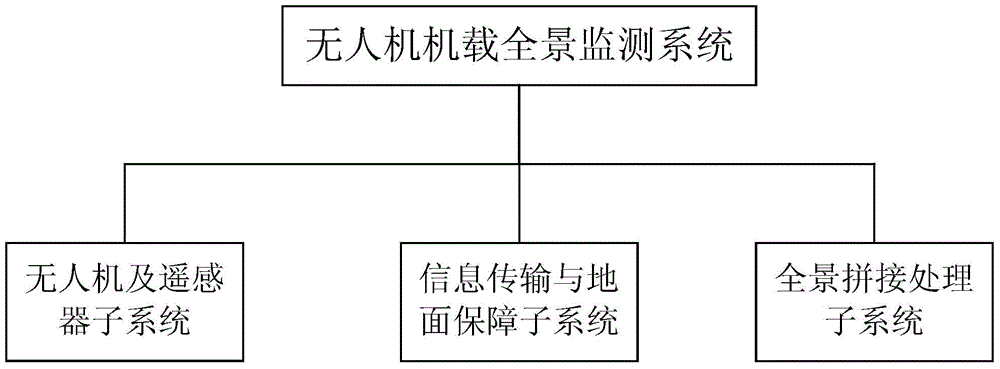
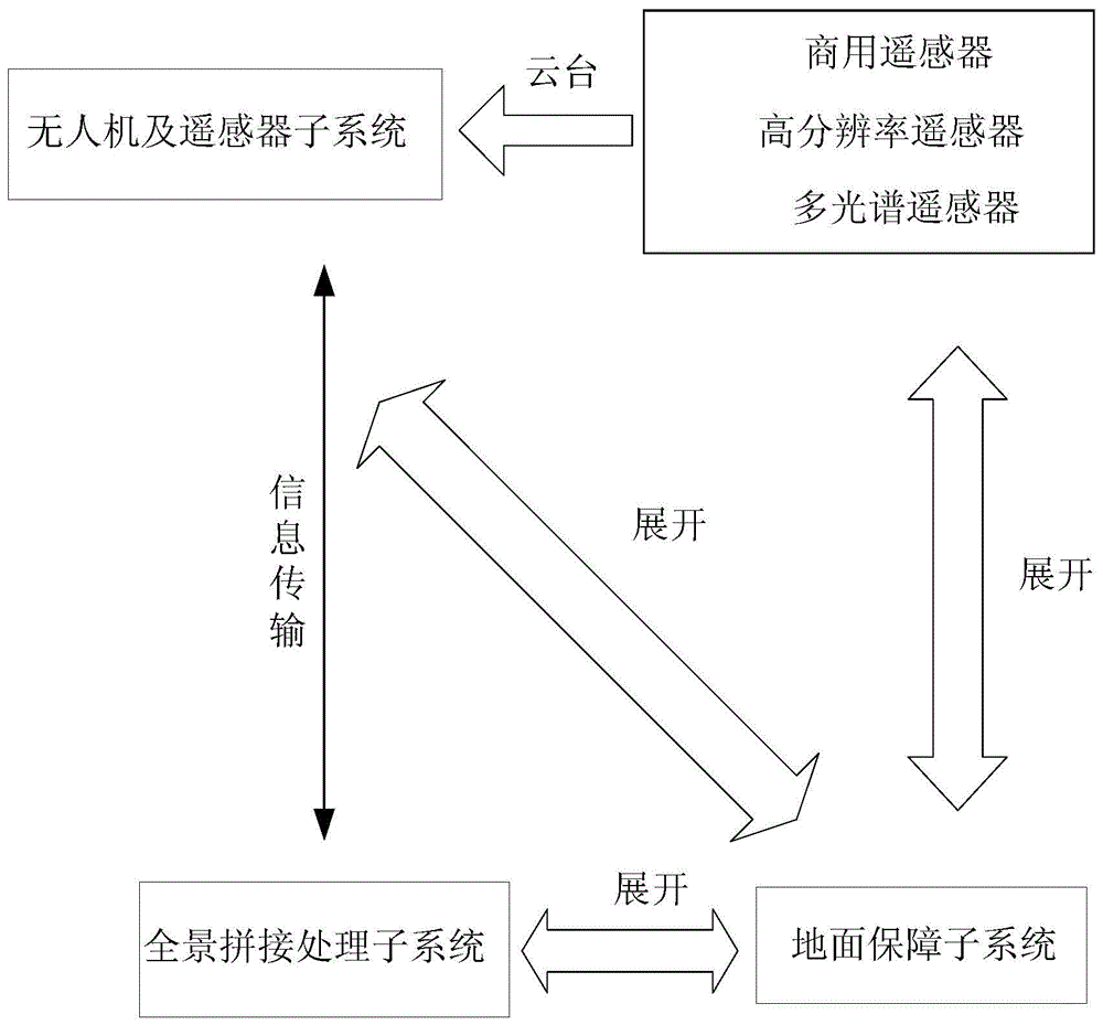
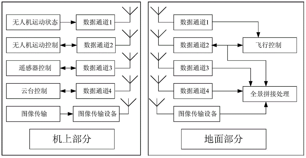
[0020] Such as figure 1 , figure 2 As shown, the UAV airborne panoramic monitoring system of the present invention includes a UAV and a remote sensor subsystem, an information transmission and ground support subsystem, and a panoramic splicing processing subsystem. The above three subsystems are all located in the vehicle cabin; The aircraft and remote sensor subsystem includes the drone and the remote sensor. The remote sensor is mounted on the drone through the remote sensor to stabilize the platform. When working, the drone flies out of the vehicle cabin and obtains the required remote sensing image information in real time; The ground support subsystem includes information transmission equipment and the ground support subsystem; the information transmission equipment is divided into a transmitting device and a receiving device, which are loaded ...


PUM


Abstract

The invention discloses an onboard panorama monitoring system of an unmanned aerial vehicle. An aerial remote sensing image is transmitted to the ground in real time, and then the real-time panorama remote sensing image monitoring system is generated. The system is composed of the unmanned aerial vehicle, a remote sensor subsystem, an information transmission and ground safeguard subsystem and a panorama stitching treatment subsystem, wherein the unmanned aerial vehicle carries a remote sensor to acquire remote sensing information, an information transmission device in the information transmission and ground safeguard subsystem is used for transmitting the state of the unmanned aerial vehicle, the state of a pan-tilt, the state of the remote sensor and control signals and downloading images, a ground safeguard device in the information transmission and ground safeguard subsystem is used for transporting and storing system devices and providing comprehensive ground safeguard for the system devices, and the panorama stitching treatment subsystem is used for achieving automatic panorama stitching of downloaded image information and real-time monitoring. The system ensures that the monitoring device can be used by nonprofessional users conveniently, is easy to operate, can be applied to various industries, and has the advantages that deployment is convenient, maneuverability is high, and the real-time property of information is high.

Description

technical field [0001] The invention belongs to the field of aerial remote sensing, in particular to an unmanned aerial vehicle-mounted panoramic monitoring system and a real-time monitoring system for generating panoramic remote sensing images. Background technique [0002] In recent years, with the development of the national economy, aerial photography has become more and more widely used, especially the country has announced the opening of low-altitude resources, so the use of drones as aerial photography platforms has become the mainstream of current development, and the use of drones as payloads The platform avoids cumbersome procedures such as applying for airspace, and the flight cost is low. [0003] On the other hand, with the explosive population growth, various natural disasters and emergencies (such as East Turkistan, Tibetan independence, etc.) occur frequently. If the progress of the situation cannot be kept abreast of, it will seriously limit the rescue asses...

Claims


Application Information

Patent Timeline
Patent Type & Authority Applications(China)
IPC IPC(8): G05D1/10
Inventor 张卫卫林招荣姚毅刚宋立国张秋丽赵曙光李鑫
Owner BEIJING RES INST OF SPATIAL MECHANICAL & ELECTRICAL TECH
Why Eureka
Try Eureka