Voltage and current signal conversion circuit

A signal conversion, voltage and current technology, applied in electrical signal transmission systems, signal transmission systems, instruments, etc., can solve problems such as inappropriate large current signal transmission

Inactive Publication Date: 2014-09-24
BEIJING MECHANICAL EQUIP INST
View PDF4 Cites 0 Cited by
  • Summary
  • Abstract
  • Description
  • Claims
  • Application Information

AI Technical Summary

Problems solved by technology

[0003] The purpose of the present invention is to provide a voltage-current signal conversion circuit, which solves the problem that the output current of

Method used


Image

  • Voltage and current signal conversion circuit

Examples


Embodiment Construction

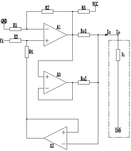
[0009] A voltage-current signal conversion circuit, comprising: a resistor R 1 , resistor R 2 , Operational amplifier A 1 , resistance R o1 , resistance R 3 , resistance R 4 and op amp A 2 , also includes: Resistor R 5 , resistance R o2 and op amp A 3 .

[0010] Resistance R 1 One end of the ground, resistor R 1 The other end is connected to the negative input terminal of the operational amplifier A1; the negative input terminal of the operational amplifier A1 is connected to the resistor R 2 Connected at one end, the resistor R 2 The other end of the resistor R 5 One end is connected to the output end of the operational amplifier A1, and the resistor R 5 The other end of the power supply V CC ; The output terminal of the operational amplifier A1 and the resistor R o1 Connected at one end, the resistor R o1 The other end of the op amp A respectively 2 The negative input of the circuit and the output of the circuit U o Connection; op amp A 3 The positive inpu...


PUM


Abstract

The invention discloses a voltage and current signal conversion circuit. The voltage and current signal conversion circuit comprises a resistor R1, a resistor R2, an operational amplifier A1, a resistor Ro1, a resistor R3, a resistor R4, an operational amplifier A2, a resistor R5, a resistor Ro2 and an operational amplifier A3. The operational amplifier A1 and a periphery circuit constitute a same-phase summation operational circuit, and a voltage follower is formed by the operational amplifier A2. The resistance values of the resistor R1, the resistor R2, the resistor R3 and the resistor R4 are equal, and a current flowing through the resistor Ro1 is equal to Ui/Ro1. The current is provided by operational amplifier A1 and a power supply VCC together. The output ability is increased by 40 mA through the resistor R5 and the operational amplifier A3. According to the voltage and current signal conversion circuit, the purpose of improving the current output ability of by two times is achieved.

Description

technical field [0001] The invention relates to a signal conversion circuit, in particular to a voltage and current signal conversion circuit. Background technique [0002] Voltage and current signal conversion circuits are widely used in the long-distance transmission of analog signals. A traditional voltage-current signal conversion circuit generally includes two operational amplifiers and peripheral resistors, one of which constitutes a non-inverting summation circuit with related resistors, and the other operational amplifier constitutes a voltage follower circuit. Due to the limitation of the output current of the operational amplifier inside the conversion circuit, the output current of the conversion circuit generally does not exceed 20mA. In many occasions, the transmission of a large current signal is required, how to improve the output current capability of the conversion circuit has become an urgent subject for further widespread application of the conversion cir...

Claims


Application Information

Patent Timeline
IPC IPC(8): G08C19/02
Inventor 孟祥适肖强王伟莉
Owner BEIJING MECHANICAL EQUIP INST
Why Eureka
Try Eureka