
A Unipolar High-Gain Microstrip Oscillator

A microstrip oscillator, high gain technology, applied in antenna coupling, radiating element structure and other directions, can solve the problems of poor directivity, insufficient bandwidth, small gain, etc., and achieve the effect of low cost, easy integration and high gain

Active Publication Date: 2016-05-04
深圳市华信微通信技术有限公司
View PDF5 Cites 0 Cited by
  • Summary
  • Abstract
  • Description
  • Claims
  • Application Information

AI Technical Summary

Problems solved by technology

[0002] Nowadays, with the wide application of satellite communication systems, research on receiving antennas for satellite communication systems emerges in an endless stream, such as monopole, dipole, helical, four-arm helical and microstrip antenna structures, all of which can be used in satellite communication systems. Among various antennas; the traditional microstrip antenna has been used in mobile communications due to its advantages of low profile, small size, light weight, conformability, easy integration, flexible feeding methods, and easy access to linear polarization and circular polarization. Satellite communications, missile telemetry, Doppler radar and many other fields have been widely used, but the limited gain has always been the defect of microstrip antennas; microstrip antennas are a new type of antennas that have been gradually developed in the past 30 years It has been widely used due to its advantages, but it also has disadvantages such as small gain, poor directivity, existence of surface waves, and insufficient bandwidth.

Method used


Image

  • A Unipolar High-Gain Microstrip Oscillator
  • A Unipolar High-Gain Microstrip Oscillator

Examples


specific Embodiment approach

[0013] The following describes the present invention in further detail with reference to the accompanying drawings and specific embodiments, without limiting the scope of implementation of the present invention.

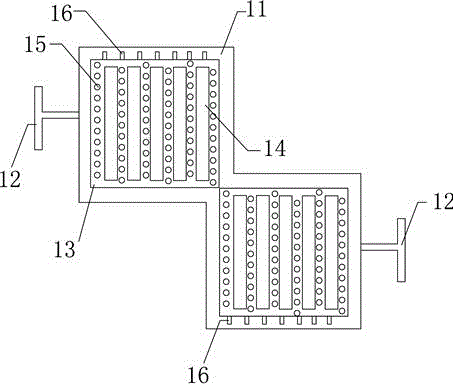
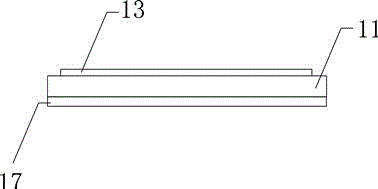
[0014] Such as Figure 1 to Figure 2 As shown, the unipolar high gain microstrip vibrator described in this embodiment includes a PCB board 11, the bottom surface of which is covered with a copper layer 17; the top surface of the PCB board 11 is provided with vibrators Circuit structure, the oscillator circuit structure includes two centrally symmetrically arranged oscillator slices 13, each oscillator slice 13 is provided with a plurality of hollow isolation slots 14 side by side, each isolation slot 14 is provided with multiple loading holes on both sides 15. Specifically, the copper layer 17 is connected to the outer core of the coaxial cable, and the loading hole 15 is connected to the inner core of the coaxial cable. Through such a reasonable structural design, dis...


PUM


Abstract

The invention discloses a unipolar high-gain microstrip vibrator; it includes two vibrator pieces arranged symmetrically in the center, each vibrator piece is provided with a plurality of hollow isolation slots side by side, and each isolation slot is provided with a plurality of Loading hole; through such a reasonable structural design, the distributed loading technology is used on the radiation element, and through the comprehensive optimization of a series of technologies, the further miniaturization of the antenna is realized, which can well meet the requirements of the current communication system. Due to the adoption of the above structure, the control of the radiation pattern of the antenna is realized, which has the characteristics of directional radiation and obtains a higher gain. Therefore, the present invention has excellent comprehensive characteristics such as high symmetry, high integration, miniaturization, good radiation characteristics, high gain, etc., and is low in cost and easy to integrate.

Description

technical field [0001] The invention relates to the field of oscillators, in particular to a unipolar high-gain microstrip oscillator. Background technique [0002] Nowadays, with the wide application of satellite communication systems, research on receiving antennas for satellite communication systems emerges in an endless stream, such as monopole, dipole, helical, four-arm helical and microstrip antenna structures, all of which can be used in satellite communication systems. Among various antennas; the traditional microstrip antenna has been used in mobile communications due to its advantages of low profile, small size, light weight, conformability, easy integration, flexible feeding methods, and easy access to linear polarization and circular polarization. Satellite communications, missile telemetry, Doppler radar and many other fields have been widely used, but the limited gain has always been the defect of microstrip antennas; microstrip antennas are a new type of anten...

Claims


Application Information

Patent Timeline
Patent Type & Authority Patents(China)
IPC IPC(8): H01Q1/38H01Q1/52
Inventor 黄昌娟
Owner 深圳市华信微通信技术有限公司
Learn More