
Vertical rotary high-voltage metal-enclosed switchgear valve mechanism

A metal-enclosed and switchgear technology, applied in the direction of pull-out switchgear, switchgear, electrical components, etc., can solve the problems of safety, reliability and convenience of unfavorable equipment, occupying limited space of the switchgear, and many transmission links, etc., to achieve the design principle Unique and novel, reasonable and compact structure, simple and safe operation

Active Publication Date: 2017-07-04
GUANGDONG GUANGTE ELECTRIC
View PDF5 Cites 0 Cited by
  • Summary
  • Abstract
  • Description
  • Claims
  • Application Information

AI Technical Summary

Problems solved by technology

[0002] At present, the handcart-type high-voltage metal-enclosed switchgear valve mechanism known in the field is distributed on the left and right sides of the cabinet, and is mainly composed of a mounting base, a shaft sleeve, a scissor-shaped arm assembly, a torsion spring, and various long rods. It is connected with the pin shaft. On the left and right sides of the circuit breaker handcart, there are also grooved push plates for driving the valve mechanism. The upper and lower valves are opened or closed when the handcart is pushed and pulled out by two vertical partitions through the transmission and lifting mechanisms on both sides. Closed, due to many transmission links and long paths, it is difficult to ensure that the two valves can be opened or closed accurately and synchronously, causing potential safety hazards
Another disadvantage of the existing valve mechanism is that there are many parts and types, and the operator needs to use the corresponding fixtures to install the parts in the cabinet one by one, which is time-consuming and labor-intensive and has a single function; Special padlock to complete, the efficiency is very low
In addition, the existing valve mechanism cabinets are arranged in a decentralized manner, which leads to the limited space occupied by the switch cabinet, which is not conducive to the miniaturization of high-voltage metal-enclosed switchgear, and is also not conducive to the improvement of equipment safety, reliability and convenience.

Method used


Image

  • Vertical rotary high-voltage metal-enclosed switchgear valve mechanism
  • Vertical rotary high-voltage metal-enclosed switchgear valve mechanism
  • Vertical rotary high-voltage metal-enclosed switchgear valve mechanism

Examples


Embodiment Construction

[0015] The content of the present invention will be further described below in conjunction with the drawings, but the actual manufacturing structure of the present invention is not limited to the embodiments shown in the drawings.

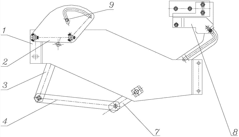
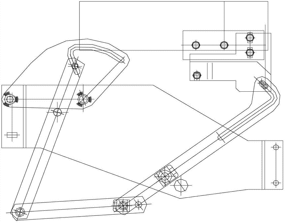
[0016] Referring to the accompanying drawings, the valve mechanism of the vertical-rotation high-voltage metal-enclosed switchgear of the present invention includes a mounting base plate 1, a linkage mechanism composed of rear, middle, and front three swing rods 3, 4, and 7, and a fan-shaped drive plate 2. And components such as the three-plate device 8 that connects valve. There are three rotation fulcrums distributed on the installation substrate 1, one of which is used to install the fan-shaped drive plate 2, and the other two rotation fulcrums are respectively used to connect the rear swing link 3 and the front swing link 7 of the linkage mechanism. The front swing link 7 in the link mechanism bar is connected with a three-plate device 8 connec...


PUM


Abstract

The invention relates to a valve mechanism of a longitudinal-rotating-type high-voltage metal-enclosed switchgear. The valve mechanism comprises an installation substrate; a connecting rod mechanism which is installed at one side of the installation substrate and includes three oscillating bars; a three-plate device which is connected with a valve of the longitudinal-rotating-type high-voltage metal-enclosed switchgear, wherein a front oscillating bar of the connecting rod mechanism is movably installed on the three-plate device; and a sector drive board which is installed at the other side of the installation substrate through a rotating support point and driven to rotate by an isolation circuit breaker, wherein the sector drive board is provided with an enclosed track groove which can drive the connecting rod mechanism to move. In practical operation, the sector drive board is driven to rotate by the isolation circuit breaker, and then the connecting rod mechanism is driven by the enclosed track groove in the sector drive board so as to drive the front oscillating bar in the connecting rod mechanism to realize large-span displacement, and the opening and closing of the valve are completed by the three-plate device which is connected with the valve of the longitudinal-rotating-type high-voltage metal-enclosed switchgear; and at the closing position of the valve, the valve mechanism can automatically lock the valve.

Description

technical field [0001] The invention belongs to the technical field of high-voltage electrical equipment, and relates to a valve mechanism of a vertically rotating high-voltage metal-enclosed switchgear. Background technique [0002] At present, the handcart-type high-voltage metal-enclosed switchgear valve mechanism known in the field is distributed on the left and right sides of the cabinet, and is mainly composed of a mounting base, a shaft sleeve, a scissor-shaped arm assembly, a torsion spring, and various long rods. It is connected with the pin shaft. On the left and right sides of the circuit breaker handcart, there are also grooved push plates for driving the valve mechanism. The upper and lower valves are opened or closed when the handcart is pushed and pulled out by two vertical partitions through the transmission and lifting mechanisms on both sides. Closed, because there are many transmission links and long paths, it is difficult to ensure that the two valves can...

Claims


Application Information

Patent Timeline
Patent Type & Authority Patents(China)
IPC IPC(8): H02B1/26H02B11/167
Inventor 杜沛屈绪民刘平平叶荣伟李芳
Owner GUANGDONG GUANGTE ELECTRIC
Learn More