Voltage reactive automatic control system channel switching method

An automatic control system, voltage and reactive power technology, applied in the direction of reactive power compensation, AC network voltage adjustment, etc., can solve the problems of long time to switch to normal mode, heavy workload of operation and maintenance personnel, and increased workload of operation and maintenance personnel, etc. Achieve the effect of improving reasonable distribution and reliable utilization, ensuring stable and safe operation, and reducing reactive power flow

Active Publication Date: 2014-09-24
STATE GRID CORP OF CHINA +1
View PDF2 Cites 1 Cited by
  • Summary
  • Abstract
  • Description
  • Claims
  • Application Information

AI Technical Summary

Problems solved by technology

[0010] (1) If the on-duty officer fails to discover the recovery of the AVC channel in time, the automatic adjustment of voltage and reactive power will be a single substation adjustment mode, and the overall coordination of voltage and reactive power in the entire network will not be possible, which will affect the optimization characteristics of voltage and reactive power in the entire network
That is, the reactive power regulation function of the entire network of the AVC system cannot be optimally utilized
[0011] (2) It is necessary to set up a special person to monitor the channel status of the AVC system. Once the channel is interrupted and restored, each substation needs to be manually switched to the city regulation mode in turn. As the number of substations connected to the AVC system increases, the workload of operation and maintenance personnel will increase. More and more, and it takes a long time to switch to the normal mode. The artificial operation efficiency affects the whole network adjustment performance of the AVC system
That is to say, this mode virtually increases the workload of operation and maintenance personnel

Method used


Image

  • Voltage reactive automatic control system channel switching method
  • Voltage reactive automatic control system channel switching method
  • Voltage reactive automatic control system channel switching method

Examples


Embodiment Construction

[0047] The channel switching method of the voltage and reactive power automatic control system provided by the present invention will be described in detail below in conjunction with the accompanying drawings and specific embodiments.

[0048] Such as Figure 6 As shown, the channel switching method of the voltage and reactive power automatic control system provided by the present invention includes the following steps executed in sequence:

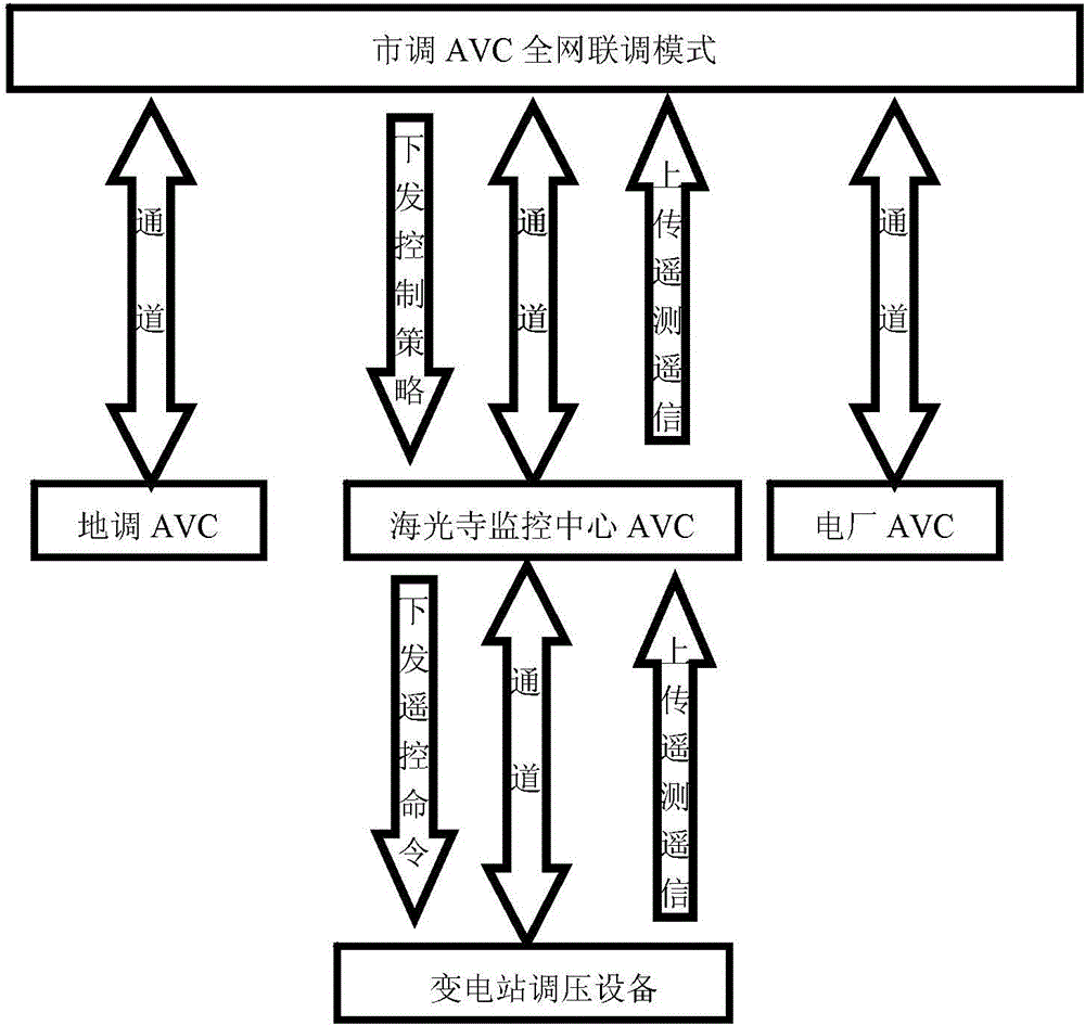
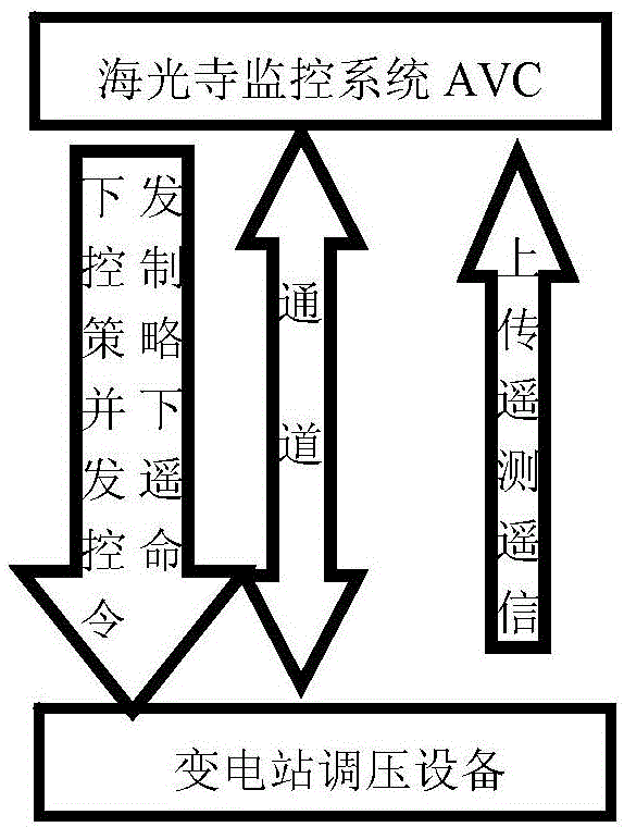
[0049] Step 1. The S01 stage of normal system operation: Under normal circumstances, the substation participating in the AVC full-network joint commissioning of the local AVC system is running in the state of remote AVC joint commissioning, and its general joint commissioning settings and branch joint commissioning settings Both execute the remote strategy;

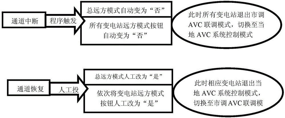
[0050] Step 2. The S02 stage of the scan cycle: it is the scan cycle when the local AVC system is running normally. Through scanning, channel abnormalities can be found in time and ...


PUM


Abstract

The invention discloses a voltage reactive automatic control system channel switching method. The method comprises the system normal operation stage, the scanning period running stage, the stage for judging whether a first exit condition is satisfied, the stage for judging whether a second exit condition is satisfied, the channel abnormal condition processing stage, the scanning period joint debugging recovery stage, the stage for judging whether the channels are recovered, the municipal dispatching joint debugging setting recovery stage, the stage for a substation to be input into municipal dispatching joint debugging, etc. According to the invention, automatic closed-loop control and real-time adjustment can be realized, the voltage stability and safe operation of the grid can be ensured; the misoperation caused by unreasonable manual adjustment and artificial omissions can be avoided; the gate reactive change can be adjusted on a real-time basis and tracked timely, the main grid voltage can be effectively supported, and the main grid voltage stability can be facilitated; and the control has the advantage of foreseeability, the time of unnecessary equipment actions can be reduced, and misoperation or frequent adjustment can be avoided.

Description

technical field [0001] The invention belongs to the technical field of computer control, and in particular relates to a channel switching method of a voltage and reactive power automatic control system. Background technique [0002] The automatic voltage and reactive power control system (AVC) of a substation monitoring center has been connected to 6 500kV substations and 24 220kV substations (more than 40 other substations with 220kV and above voltage levels will be connected to this AVC system in succession), and the local realization At the same time as the automatic control function of voltage and reactive power, it completes the joint debugging with the municipal AVC system, and can realize real-time automatic adjustment and coordinated control according to the voltage and reactive power distribution status of the municipal power grid. Compared with manual operation, its adjustment strategy is more rational and intelligent. The network-wide optimization feature improves...

Claims


Application Information

Patent Timeline
Patent Type & Authority Applications(China)
IPC IPC(8): H02J3/16
CPCY02E40/30
Inventor 白慧宋建新吕跃沈浮陈天恒王刚宋维斌
Owner STATE GRID CORP OF CHINA
Why Eureka
Try Eureka