
Dimming method of phase-cut dimming control circuit based on LED lamp

A phase-cut dimming and control circuit technology, applied in the field of LED lighting, to reduce output current, avoid output LED load flicker, and eliminate high-frequency noise

Active Publication Date: 2016-05-11
WUXI SEASTAR LIGHTING CO LTD
View PDF6 Cites 0 Cited by
  • Summary
  • Abstract
  • Description
  • Claims
  • Application Information

AI Technical Summary

Problems solved by technology

[0003] In order to solve the problem that there is no phase-cut dimming circuit suitable for driving constant voltage and constant current LED products in the prior art, the present invention provides a dimming method based on a phase-cut dimming control circuit for LED lamps

Method used


Image

  • Dimming method of phase-cut dimming control circuit based on LED lamp
  • Dimming method of phase-cut dimming control circuit based on LED lamp
  • Dimming method of phase-cut dimming control circuit based on LED lamp

Examples


Embodiment Construction

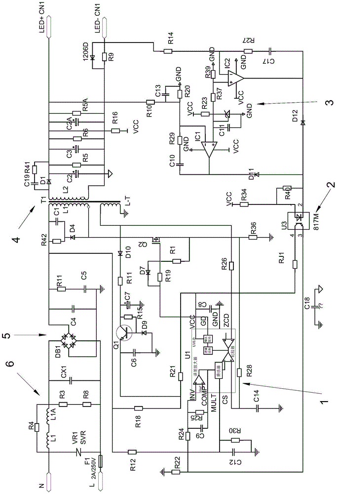
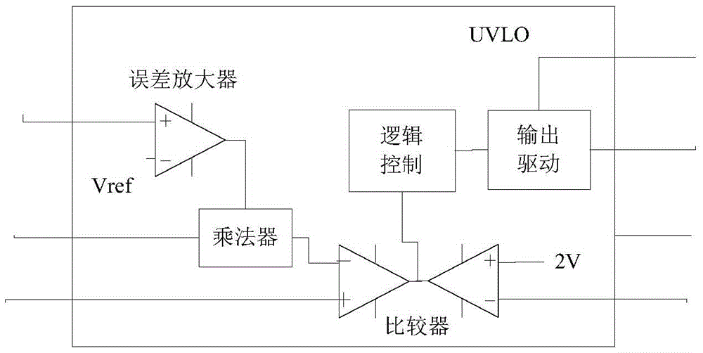
[0032] figure 1 It is a specific circuit diagram that can implement the present invention. figure 1 For the circuit diagram of the logic circuit part in figure 2 shown.

[0033] like figure 1 , figure 2 As shown, the implementation is as follows:

[0034] (1) Constant voltage phase-cut dimming:

[0035] The input alternating current is rectified by the bridge rectifier circuit DB1 and then connected to the resistor R18, and the resistor R18 is connected to the drive terminal of the output driver in the logic circuit to provide starting power for the logic circuit. The output end of the logic circuit output driver outputs a modulated pulse signal and is connected to the gate of the field effect transistor Q2 to drive the field effect transistor Q2 to conduct. The primary winding L1 of the transformer T1 can store energy and can generate excitation current. The primary winding L1 of the transformer T1 connects the field effect transistor Q2 to the resistor R36, so that ...


PUM


Abstract

The invention discloses a phase-sectioning dimming control circuit for an LED lamp and a dimming method of the phase-sectioning dimming control circuit. A logic circuit in the circuit is used for performing multiplication on error amplification signals of input voltages and output currents collected after rectification, phase sectioning is performed on collected rectification voltage signals after phase sectioning is performed on the input voltages, obtained phase-sectioning signals are used for controlling breakover time of a field-effect tube after multiplication is performed on the rectification voltage signals and the output signals of an error amplifier, and the larger the phase sectioning angle is, the smaller the energy transmitted by a transformer is. When a load is constant-voltage characteristic load, output voltages are reduced in the phase sectioning process; when the load is a constant-current characteristic load, the output currents are reduced in the phase sectioning process. According to the phase-sectioning dimming control circuit and the dimming method, on the basis of constant-voltage and constant-current control over power output, the phase-sectioning dimming function is achieved through dummy loads, signal collecting, processing and other means, and therefore the whole circuit system achieves the purpose of compatibility of constant-voltage phase-sectioning dimming and constant-current phase-sectioning dimming.

Description

technical field [0001] The invention relates to the field of LED lighting, in particular to a dimming method based on a phase-cut dimming control circuit of an LED lamp. Background technique [0002] At present, the LED lighting industry is developing rapidly, and the market's pursuit of energy-saving benefits has led to an increasing demand for LED dimming. One of the commonly used dimming methods of phase-cut dimming, this method is to change the sinusoidal waveform by adjusting the conduction angle of each half-wave of the alternating current, thereby changing the effective value of the alternating current, so as to achieve the purpose of dimming, and also This is called "chopper" dimming. At present, the phase-cut dimming LED drivers on the market are mainly aimed at LED products driven by constant current mode, but there are also some LED products that require constant voltage mode drive, such as LED light strips, and there is no one in the existing technology that can...

Claims


Application Information

Patent Timeline
Patent Type & Authority Patents(China)
IPC IPC(8): H05B37/02
Inventor 郭穗王邦虎
Owner WUXI SEASTAR LIGHTING CO LTD
Learn More