Few mode optical fibers for mode division multiplexing

A technology of few-mode fiber and fiber core, which is applied in the field of few-mode fiber and can solve problems such as difficulty in demultiplexing optical signals

Active Publication Date: 2014-09-24
CORNING INC
View PDF6 Cites 30 Cited by
  • Summary
  • Abstract
  • Description
  • Claims
  • Application Information

AI Technical Summary

Problems solved by technology

These large delay differences make it difficult to dem

Method used


Image

  • Few mode optical fibers for mode division multiplexing
  • Few mode optical fibers for mode division multiplexing
  • Few mode optical fibers for mode division multiplexing

Examples


Embodiment Construction

[0026] Reference will now be made in detail to various embodiments of optical fibers for use as long-distance transmission optical fibers, examples of which are illustrated in the accompanying drawings. Wherever possible, the same reference numbers will be used throughout the drawings to refer to the same or like parts.

[0027] the term

[0028] The following terminology will be used herein to describe optical fibers, some of which parameters are introduced and defined in conjunction with various exemplary embodiments as follows:

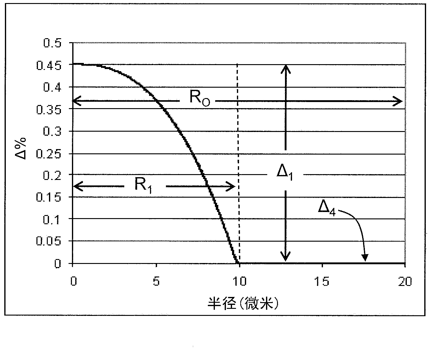
[0029] Herein, the term "refractive index profile" refers to the relationship between the refractive index or the relative refractive index and the radius of the optical fiber.

[0030] The term "relative refractive index", as used herein, is defined as:

[0031] △(r)%=100x[n(r) 2 –n REF 2 )] / 2n(r) 2 ,

[0032] Unless otherwise indicated, n(r) is the refractive index at radius r. Relative refractive indices are defined at 1550 nm unless oth...


PUM

PropertyMeasurementUnit
Radial thicknessaaaaaaaaaa
Radiusaaaaaaaaaa

Abstract

A few mode optical fiber suitable for use in a mode division multiplexing (MDM) optical transmission system is disclosed. The optical fiber has a graded-index core with a radius R1 in the range from 8 [mu]m to 14 [mu]m, an alpha value greater than or equal to about 2.3 and less than about 2.7 at a wavelength of 1550 nm, and a maximum relative refractive index Delta1MAX from about 0.3% to about 0.6% relative to the cladding. The optical fiber also has an effective area greater than about 90 [mu]m2 and less than about 160 [mu]m2. The core and cladding support only the LP01 and LP11 modes at wavelengths greater than 1500 nm. The cladding has a maximum relative refractive index Delta4MAX such that Delta1MAX>Delta4MAX, and the differential group delay between the LP01 and LP11 modes is less than about 0.5 ns/km at a wavelength of 1550 nm.

Description

[0001] Cross References to Related Applications [0002] This application claims the benefit of priority to US Provisional Application 61 / 523552, filed August 15, 2011, the content of which this application relies upon and which is hereby incorporated by reference in its entirety. [0003] field [0004] This specification relates generally to optical fibers, and more particularly to few-mode optical fibers for mode division multiplexing (MDM). Background technique [0005] The explosive growth in the volume and diversity of multimedia telecommunication applications is driving the speed demands of Internet traffic and triggering research on backbone fiber optic communication links. Receivers based on coherent communication and electronic digital signal processing (DSP) have been accepted as the next-generation standard for long-haul systems in recent years due to their flexibility, scalability, and ability to compensate various transmission impairments, including fiber nonlin...

Claims


Application Information

Patent Timeline
IPC IPC(8): G02B6/02
CPCG02B6/02019G02B6/03627G02B6/0288G02B6/0281G02B6/0365G02B6/02047G02B6/028
Inventor S·R·别克汉姆M-J·李D·A·诺兰J·王
Owner CORNING INC
Why Eureka
Try Eureka