Method and device for controlling turbines in order to control output pressures

A technology of output pressure and turbine, applied in the direction of respirator, etc., can solve the problems of high hardware control cost, short turbine use time, high user cost, and achieve the effect of convenient operation, lower system cost and less wear and tear.

Active Publication Date: 2014-10-01
BEIJING AEONMED
View PDF7 Cites 4 Cited by
  • Summary
  • Abstract
  • Description
  • Claims
  • Application Information

AI Technical Summary

Problems solved by technology

[0003] Although the above turbine control method with the goal of controlling the output pressure realizes the control of the output pressure, the cost of hardware control is relatively high due to the addition of a proportional valve in the system.
At the same time, since the turbine is always in a state of relatively high-speed operation, for such a mechanical structure, the wear and tear is relatively large, resulting in a short

Method used


Image

  • Method and device for controlling turbines in order to control output pressures
  • Method and device for controlling turbines in order to control output pressures
  • Method and device for controlling turbines in order to control output pressures

Examples


Embodiment Construction

[0041] The technical solutions of the present invention will be further explained through specific implementations below.

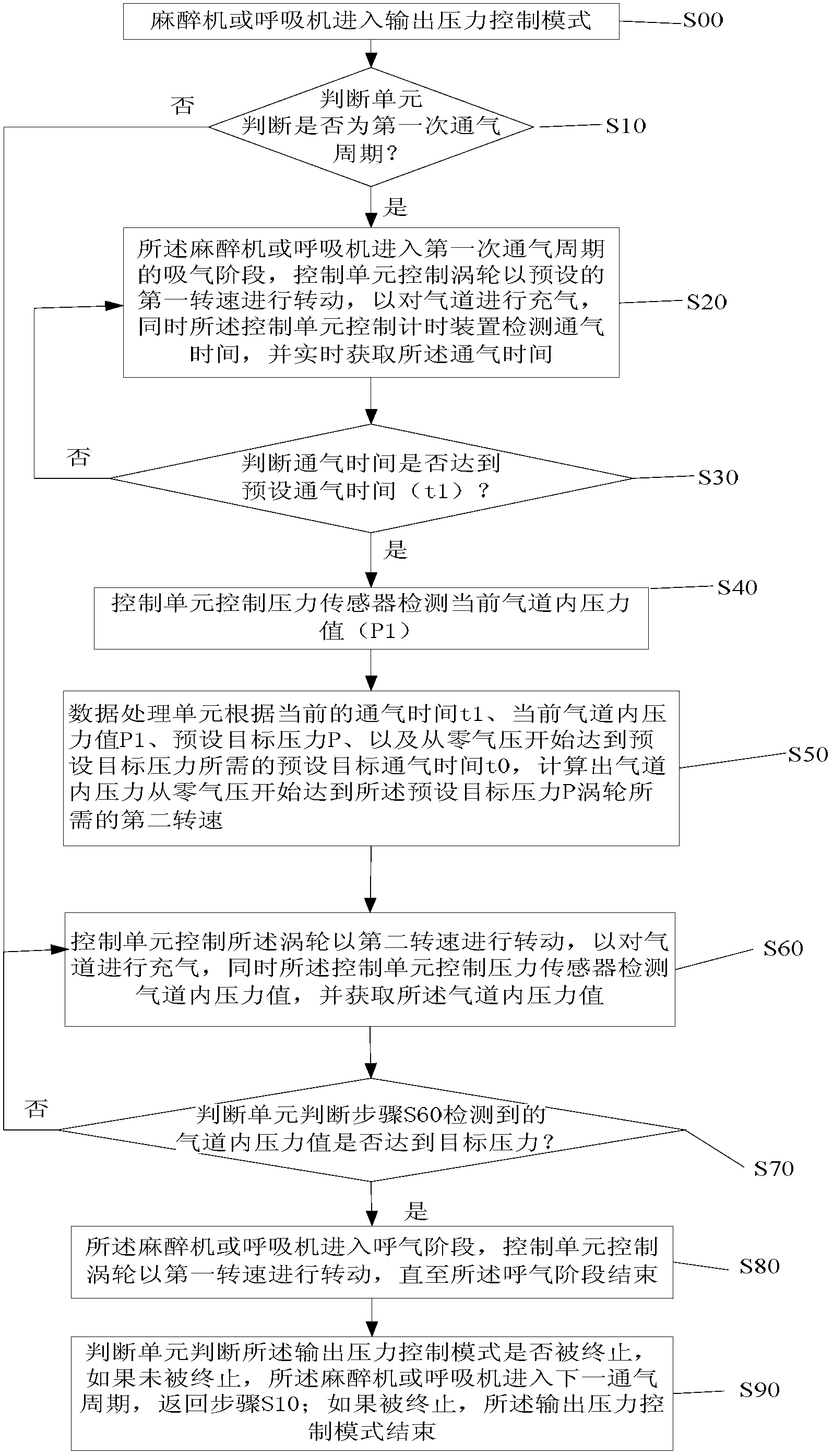
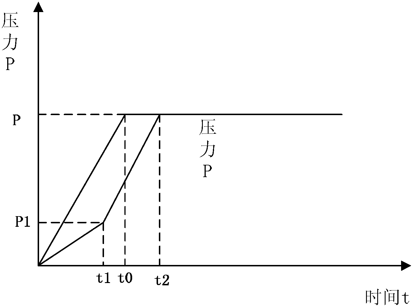
[0042] The present invention provides a turbine control method aiming at controlling output pressure. The method aims at controlling the actual rotation speed of the turbine, and achieves the effect of the minimum turbine rotation speed required for the pressure in the airway to reach the preset target pressure within the preset target ventilation time. First, obtain the required minimum turbine speed, that is, the target speed, through certain measurement steps. In the subsequent ventilation, you can directly ventilate with the target turbine speed calculated from the first ventilation. The calculation method of the turbine target speed is described in detail below.

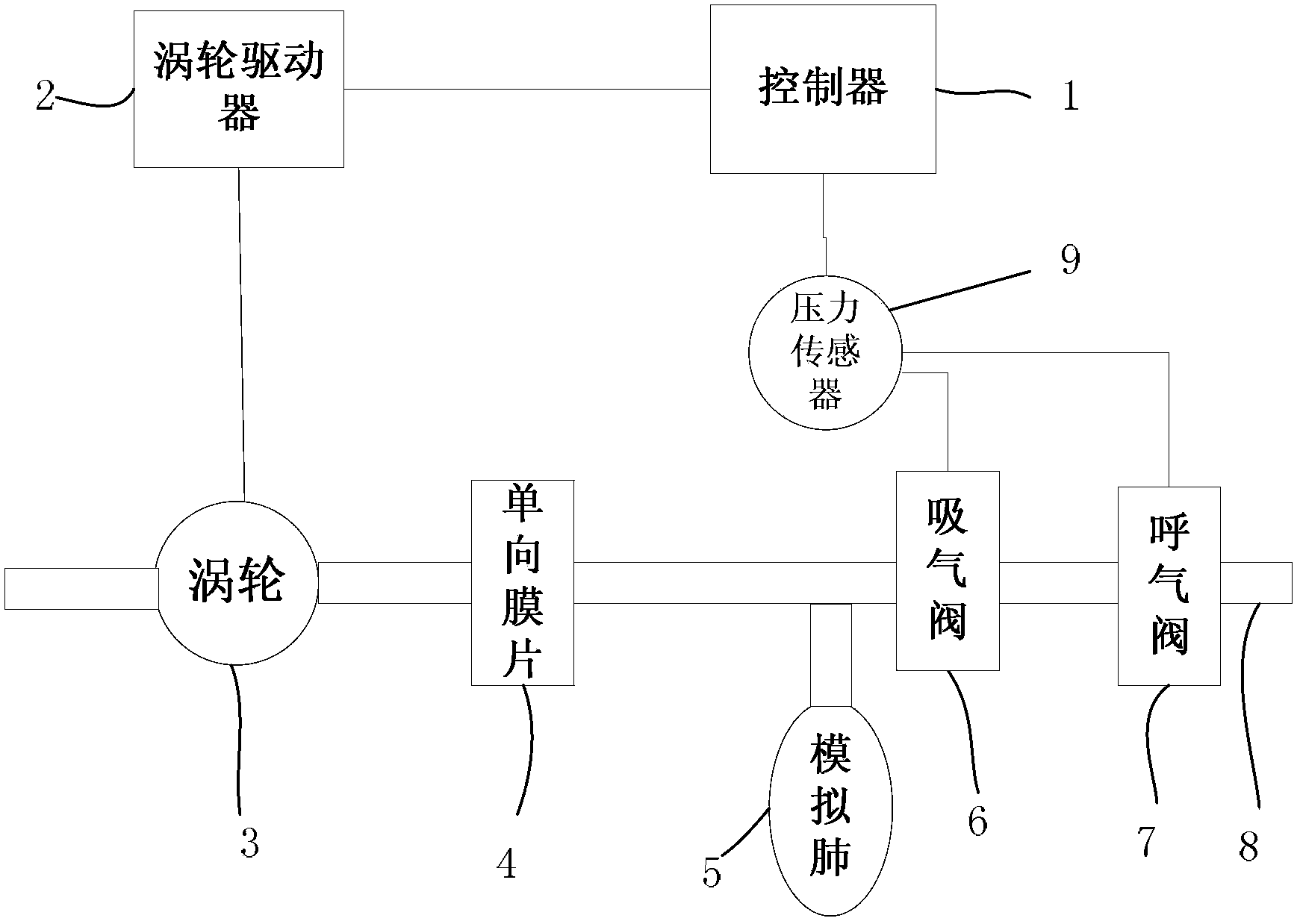
[0043] figure 2 Realization provided for the invention figure 1 The structure diagram of the gas supply system of the method. Such as figure 2 As shown, in terms of hardware, the gas supply...


PUM


Abstract

The invention discloses a method and a device for controlling turbines in order to control output pressures. The method for controlling the turbines includes steps of S00, enabling anesthesia machines or respirators to enter output pressure control modes; S10, judging whether the anesthesia machines or the respirators enter the output pressure control modes for the first time or not, executing a step S20 if the anesthesia machines or the respirators enter the output pressure control modes for the first time, or executing a step S70 if the anesthesia machines or the respirators do not enter the output pressure control modes for the first time; S20, inflating airways by the aid of the turbines at preset lowest rotation speeds and detecting the ventilation time; S30, judging whether the ventilation time is equal to a preset ventilation time threshold value or not, executing a step S40 if the ventilation time is equal to the preset ventilation time threshold value, or executing the step S20 if the ventilation time is not equal to the preset ventilation time threshold value; S40, detecting internal pressure values of the airways; S50, computing required second rotation speeds of the turbines when internal pressures of the airways are increased from the original zero and then are equal to preset target pressures P by the aid of the turbines; S60, enabling the turbines to rotate at the second rotation speeds so as to inflate the airways; S70, judging whether the internal pressure values of the airways are equal to the preset target pressures P or not; S80, enabling the anesthesia machines or the respirators to enter expiration stages; S90, judging whether the output pressure control modes are terminated or not, and enabling the anesthesia machines or the respirators to enter next ventilation periods if the output pressure control modes are not terminated.

Description

Technical field [0001] The present invention relates to the field of medical equipment, and more specifically, to a turbine control method and its control device aiming at controlling output pressure. Background technique [0002] In current medical equipment, in order to reduce the size of the equipment and at the same time reduce the dependence on external air compressors, medical equipment such as ventilators and anesthesia machines that use turbines as a means of providing compressed air are becoming more and more popular. However, in the prior art, due to insufficient software control algorithms, in general, the turbine always works at a higher speed. That is to say, the excess output pressure is provided through the additional high speed, and the excess pressure exceeding the target pressure is balanced by the method of venting. For example, the turbine speed is divided into 4 speeds according to the entire turbine speed range from low to high, and the specific speed that ...

Claims


Application Information

Patent Timeline
IPC IPC(8): A61M16/00A61M16/01
Inventor 刘建军
Owner BEIJING AEONMED
Why Eureka
Try Eureka