
Engineering machinery brake steering system

A technology of steering system and construction machinery, applied in the direction of fluid steering mechanism, hydraulic brake transmission device, etc., can solve the problems of short braking distance, complex working conditions, high braking system requirements, etc., to ensure the ability to control the direction, protect the The effect of life safety and cost advantage is obvious

Active Publication Date: 2014-10-01
XCMG CONSTR MACHINERY
View PDF6 Cites 1 Cited by
  • Summary
  • Abstract
  • Description
  • Claims
  • Application Information

AI Technical Summary

Problems solved by technology

[0005] 1. The mass of the car body is large, and it is much larger than that of a family car. The whole machine has a strong inertia when driving, and it is not easy to be braked. Therefore, it has high requirements on the braking system.
[0006] 2. The speed of the vehicle is low. Generally, the maximum speed of no-load does not exceed 40km / h, which is far lower than the maximum speed of a car. It is not mainly used for road transportation, but mainly for earth and stone construction operations.
[0007] 3. The braking distance is short. Once the driver steps on the brake, the braking force will reach the maximum, so that the tires will be locked and the slip distance will be the shortest
However, the working conditions used by each customer are very complicated. For the heavy load downhill working condition of the whole machine, that is, when braking, the problem of turning but not being able to turn has become a defect of the traditional design concept.

Method used


Image

  • Engineering machinery brake steering system
  • Engineering machinery brake steering system
  • Engineering machinery brake steering system

Examples


Embodiment Construction

[0045] The following is a specific embodiment of the present invention, and the present invention will be further described in conjunction with the accompanying drawings.

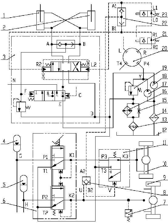
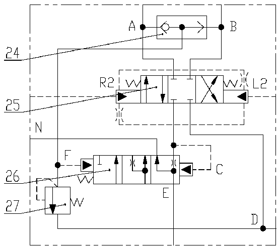
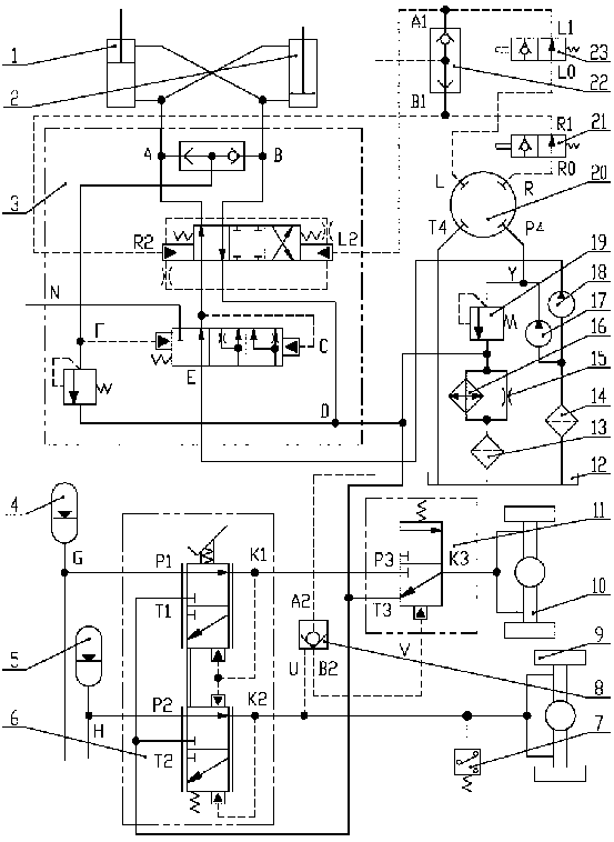
[0046] Such as figure 1 and figure 2 As shown, it includes a left steering cylinder 1, a right steering cylinder 2, a steering valve 3, a foot brake valve 6, a rear drive axle 9, a front drive axle 10, a steering gear 20 and a fuel tank 12; the steering valve 3 includes a second shuttle valve 24. Amplifying valve 25, second priority valve 26 and second relief valve 27.

[0047] The outlet of the small chamber of the left steering cylinder 1 and the outlet of the large chamber of the right steering cylinder 2 are simultaneously connected to port B of the second shuttle valve 24 in the steering valve 3, and the outlet of the large chamber of the left steering cylinder 1 is connected to the outlet of the small chamber of the right steering cylinder 2 at the same time Connect to the A port of the second shut...


PUM


Abstract

The invention discloses an engineering machinery brake steering system which can preferentially swerve front wheels and brakes rear wheels simultaneously when engineering machinery slides down a slope under a heavy load and four wheels of the engineering machinery are in locking status. The engineering machinery brake steering system is characterized in that a first priority valve is connected into a braking oil circuit of a front bridge (steering bridge) of the engineering machinery, functions of the first priority valve are equivalent to functions of a connected rubber tube and the braking oil circuit of the front bridge remains in connection status when the engineering machinery does not swerve, normal braking of the front bridge and a rear bridge can be simultaneously achieved after the front bridge is braked, and when the front bridge needs to swerve, the first priority valve rapidly cuts off the braking oil circuit of the front bridge and enables pressure oil in the front bridge to directly flow back to an oil tank under functions of pressure of control oil, and therefore braking pressure of the front bridge is reduced to 0, and simultaneously the front bridge can smoothly achieve normal steering, and the rear wheels remain in braking status. After the steering is completed, the first priority valve is enabled to return under functions of a return spring, circulation status of the pressure oil in the front bridge is instantly recovered, and then the front bridge and the rear bridge are simultaneously braked.

Description

technical field [0001] The invention relates to a construction machine with full hydraulic steering and four-wheel drive, in particular to a construction machine capable of performing front wheel priority steering and rear wheel braking at the same time when the construction machine is descending with a heavy load and the four wheels are locked. Mechanical brake steering system. Background technique [0002] When the construction machinery is under heavy load, when driving on a flat road, the driver steps on the brake pedal, and the four tires of the whole machine are often completely locked. It is a heavy load, and the strong inertia of the whole machine makes the driver need to step on the brake all the time to completely lock the wheels to control the speed of the whole machine. Since the driving speed of construction machinery is much lower than that of cars, the maximum no-load speed generally does not exceed 40km / h, and the heavier the machine, the lower the maximum n...

Claims


Application Information

Patent Timeline
Patent Type & Authority Applications(China)
IPC IPC(8): B62D5/06B62D5/08B60T11/24
Inventor 王小虎韩标郭军胜沈勇范小童谢朝阳黄新程然张爱霞
Owner XCMG CONSTR MACHINERY
Learn More