a line device

A pay-off device and state-of-the-art technology, used in transportation and packaging, conveying filamentous materials, thin material handling, etc., can solve problems such as inadequate management, loud startup noise, mechanical vibration, etc., achieve a simple and practical structure, and improve production. Efficiency, the effect of faster loading

Active Publication Date: 2017-05-17
JIANGSU KAIDA CABLE
View PDF7 Cites 0 Cited by
  • Summary
  • Abstract
  • Description
  • Claims
  • Application Information

AI Technical Summary

Problems solved by technology

However, these structures also have certain disadvantages
The upper top of the shaft type is too cumbersome; the shaftless type has one more lift, and can have a sufficient height; the shafted pay-off device with bearing bushes allows employees to run without the top, which will cause jumping and dry friction, which will seriously damage the plate. For the top inner hole, the upper machine vibrates due to slight loose clamping, which will cause loud startup noise and mechanical vibration. In severe cases, it will fly out of the equipment during high-speed rotation, causing equipment damage and personnel safety. There are generally similar in the same industry. Phenomenon, poor management is even worse

Method used


Image

  • a line device
  • a line device
  • a line device

Examples


Embodiment Construction

[0022] The invention discloses a wire pay-off device, which solves the phenomenon that the existing equipment damages the work plate inadvertently, improves the guarantee for safe production, and reduces unnecessary losses.

[0023] The technical solutions in the embodiments of the present invention will be described in detail below with reference to the drawings in the embodiments of the present invention.

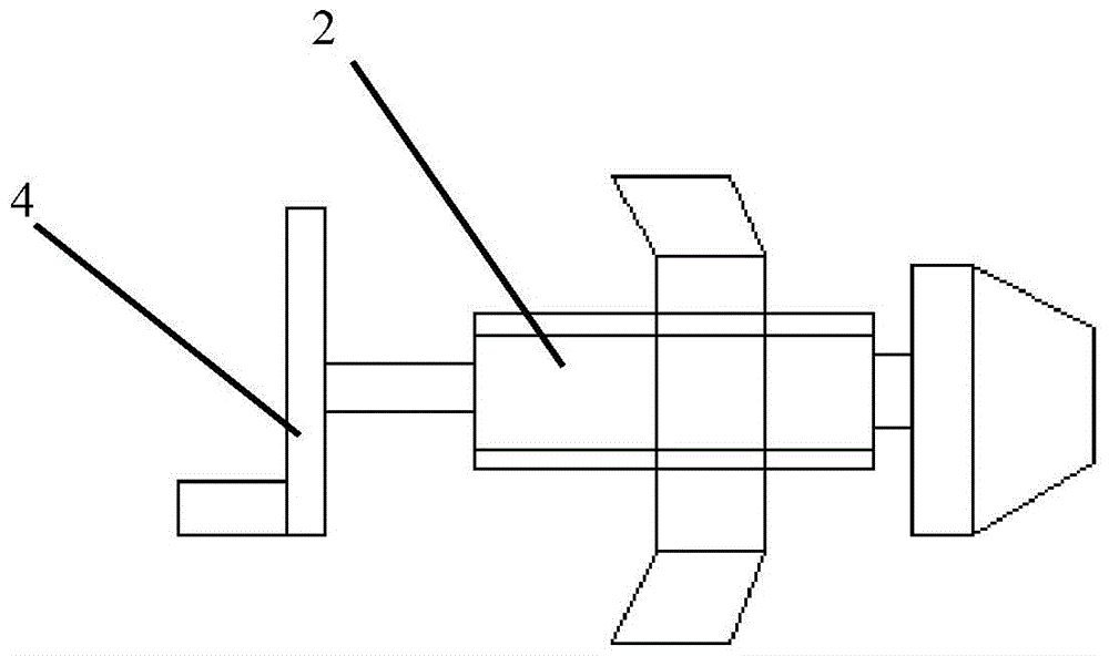
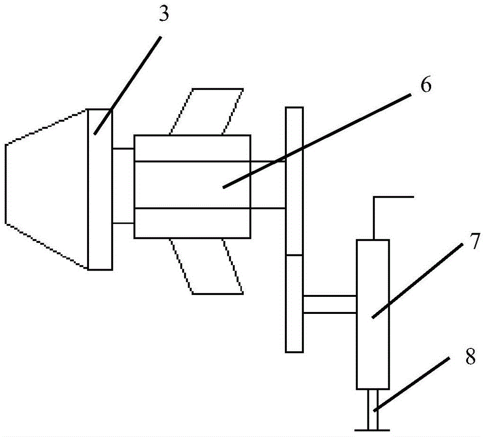
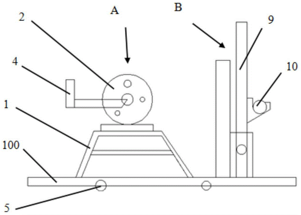
[0024] like figure 1 and figure 2 As shown, the pay-off device disclosed in the present invention includes an iron plate 100 , a pay-off frame 1 disposed on the iron plate 100 , and a pay-off tip 2 and a push rod 3 disposed on the pay-off frame 1 . The pay-off top 2 is a trapezoidal anti-thread propelling rod. The head of the pay-off top 2 is designed in a conical shape, and the taper is used to lift the tray so that it can run 1-1.5 cm above the ground, and there is no need to reconnect with the original The device is lifted, and the screw rod can be avoided from shak...


PUM


Abstract

The invention discloses a paying-off device. The paying-off device comprises an iron plate as well as a paying-off tip and a pushing rod which are arranged on the iron plate, wherein the paying-off tip is a trapezoidal tooth left-hand thread pushing rod; the head of the paying-off tip presents a conical design; the pushing rod comprises a chain wheel, a chain connected with the chain wheel, an action brake for controlling the chain wheel to stop a movement, an action belt connected with the action brake, and an adjustment rod for adjusting the action brake; the paying-off device is a dual-purpose paying-off frame, and further comprises an n-shaped lever, a bearing bush pin element connected with the n-shaped lever, and a pull ring self-locking device. The paying-off device disclosed by the embodiment of the invention is simple and practical in structure, accelerated in tray loading speed, and stable in action; a tray cannot fall off due to inertia after scram, and staffs cannot operate if dropping out a program, thus the working tray is comprehensively protected, production equipment in next step is protected, potential safety hazards are avoided, and production efficiency is increased simultaneously.

Description

technical field [0001] The invention relates to the technical field of pay-off, in particular to a pay-off device. Background technique [0002] The existing pay-off device is basically a wheeled lifting device in the direction of the screw mandrel and a lever-locked pay-off device. But these structures also have certain disadvantages. The upper top of the shaft type is too cumbersome; the shaftless type has one more lift, and can have a sufficient height; the shafted pay-off device with bearing bushes allows employees to run without the top, which will cause jumping and dry friction, which will seriously damage the plate. For the top inner hole, the upper machine vibrates due to slight loose clamping, which will cause loud startup noise and mechanical vibration. In severe cases, it will fly out of the equipment during high-speed rotation, causing equipment damage and personnel safety. There are generally similar in the same industry. The phenomenon is even worse if the ma...

Claims


Application Information

Patent Timeline
Patent Type & Authority Patents(China)
IPC IPC(8): B65H49/18
Inventor 刘学军蒋军熙卫宇
Owner JIANGSU KAIDA CABLE
Why Eureka
Try Eureka