
Shower water heat exchanging floor drainage

A technology for shower water and floor drain, which is applied to waterway systems, water supply devices, drainage structures, etc., can solve the problems of high cost, high installation difficulty, and difficulty in popularization, etc., and achieves the effects of low cost, simple structure and convenient installation.

Inactive Publication Date: 2014-10-01
邬汉镇
View PDF6 Cites 1 Cited by
  • Summary
  • Abstract
  • Description
  • Claims
  • Application Information

AI Technical Summary

Problems solved by technology

The water heat exchange device needs to be installed separately, which is difficult to install and is not suitable for modification
Moreover, the structure of the water heat exchanger is complicated, the cost is high, and it is difficult to popularize

Method used


Image

  • Shower water heat exchanging floor drainage
  • Shower water heat exchanging floor drainage

Examples


Embodiment Construction

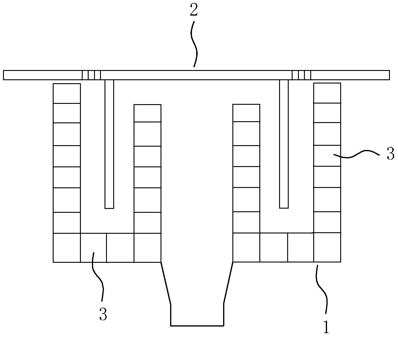
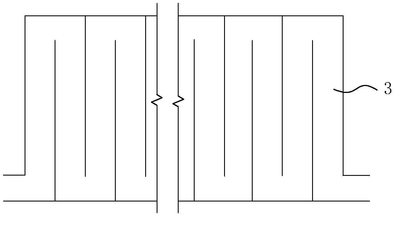
[0010] Such as Figure 1-2 As shown, a shower water heat exchange floor drain includes a trap main body 1 and a bowl sieve plate 2 . In the present invention, a curved pipe 3 is arranged in the wall of the curved groove of the main body 1 of the water trap, and both the main body 1 and the pipe 3 of the water trap are made of heat-conducting materials.

[0011] Specifically, such as figure 1 As shown, the curved groove wall of the main body 1 of the water trap is set to be hollow, and the cavity is divided into several circles of horizontally surrounding pipes 3. Following the distribution of the pipes 3, these pipes 3 are connected in series from end to end in sequence, and respectively reserved A water inlet and a water outlet. or, if figure 2 As shown, the side cavity of the curved groove wall of the main body 1 of the water trap is divided into several vertical pipes 3, and the bottom cavity is divided into surrounding pipes 3, and these pipes 3 are connected in series...


PUM


Abstract

The invention discloses a shower water heat exchanging floor drainage, which comprises a water lock main body and a buckle bowl screen plate, wherein a turning pipeline is arranged in a bending groove wall of the water lock main body; the water lock main body and the pipeline are made of heat conducting materials. According to the shower water heat exchanging floor drainage, as the turning pipeline is arranged in the bending groove wall of the water lock of the floor drainage, when the shower hot water flows through the floor drainage, water flowing through the turning pipeline can be heated, the water in the pipeline absorbs residual heat of the shower hot water and flows into a water storing tank, so that the purpose of recovery of waste heat of the shower hot water is realized. The heat exchanging floor drainage has the advantages that the structure is simple, the cost is low, the popularization is facilitated and the assembly is convenient; the heat exchanging floor drainage is particularly suitable for conventional improvement.

Description

technical field [0001] The invention relates to the technical field of floor drains, in particular to a floor drain capable of recovering waste heat from shower hot water. Background technique [0002] Most of the waste hot water when people take a shower is directly drained, but the waste hot water in the shower also contains a large amount of waste heat. In the process of draining the waste hot water, a large amount of heat is also discharged, resulting in waste. Obviously, this violates the social development purpose of energy conservation and emission reduction. [0003] At present, there are also recovery and utilization of waste heat from shower waste hot water, but most of them use water heat exchange devices to recover waste heat. The water heat exchange device needs to be installed separately, which is difficult to install and is not suitable for modification. Moreover, the structure of the water heat exchanger is complicated, the cost is high, and it is difficult...

Claims


Application Information

Patent Timeline
IPC IPC(8): E03F5/04
Inventor 邬汉镇
Owner 邬汉镇
Learn More