
Direct-current fan structure

A technology of electric fans and DC motors, which is applied in the field of structural innovation of DC electric fans, can solve problems such as energy consumption, consumption, and energy loss, and achieve the effect of reducing energy loss

Inactive Publication Date: 2014-10-01
黄进成
View PDF6 Cites 0 Cited by
  • Summary
  • Abstract
  • Description
  • Claims
  • Application Information

AI Technical Summary

Problems solved by technology

In this way, the maximum space between the fan blade and the housing must be occupied as a whole, and more raw materials need to be used to manufacture the aforementioned housing and motor, resulting in the first energy loss
Secondly, it is known that AC motors use AC 110 / 220 volts of electricity, and more power energy must be consumed to drive the fan blades, resulting in a second energy consumption
Furthermore, when the AC motor is running, it is easy to generate high temperature, so that the temperature of the airflow at the front of the fan blade may be higher than the room temperature. As a result, part of the airflow generated by the fan blade must be used for cooling the motor, which directly reduces the cooling efficiency of the fan. Only by consuming more electric energy can the fans be able to exert their proper performance, resulting in the third disadvantage of energy loss

Method used


Image

  • Direct-current fan structure
  • Direct-current fan structure
  • Direct-current fan structure

Examples


Embodiment Construction

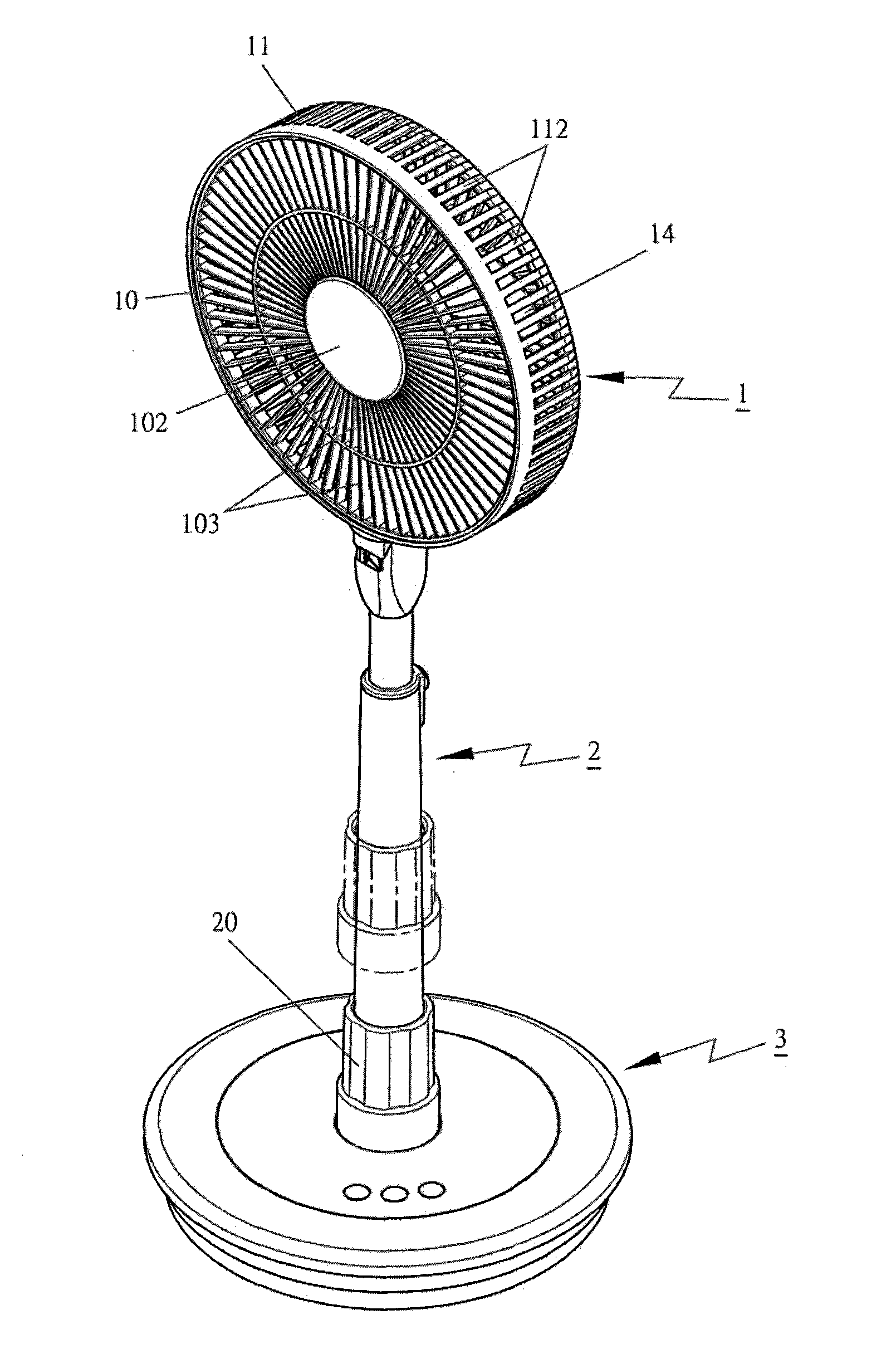
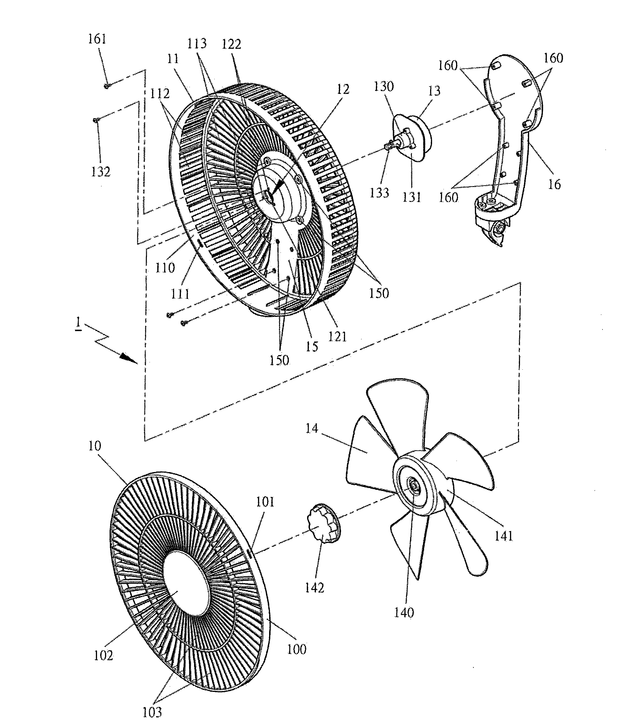
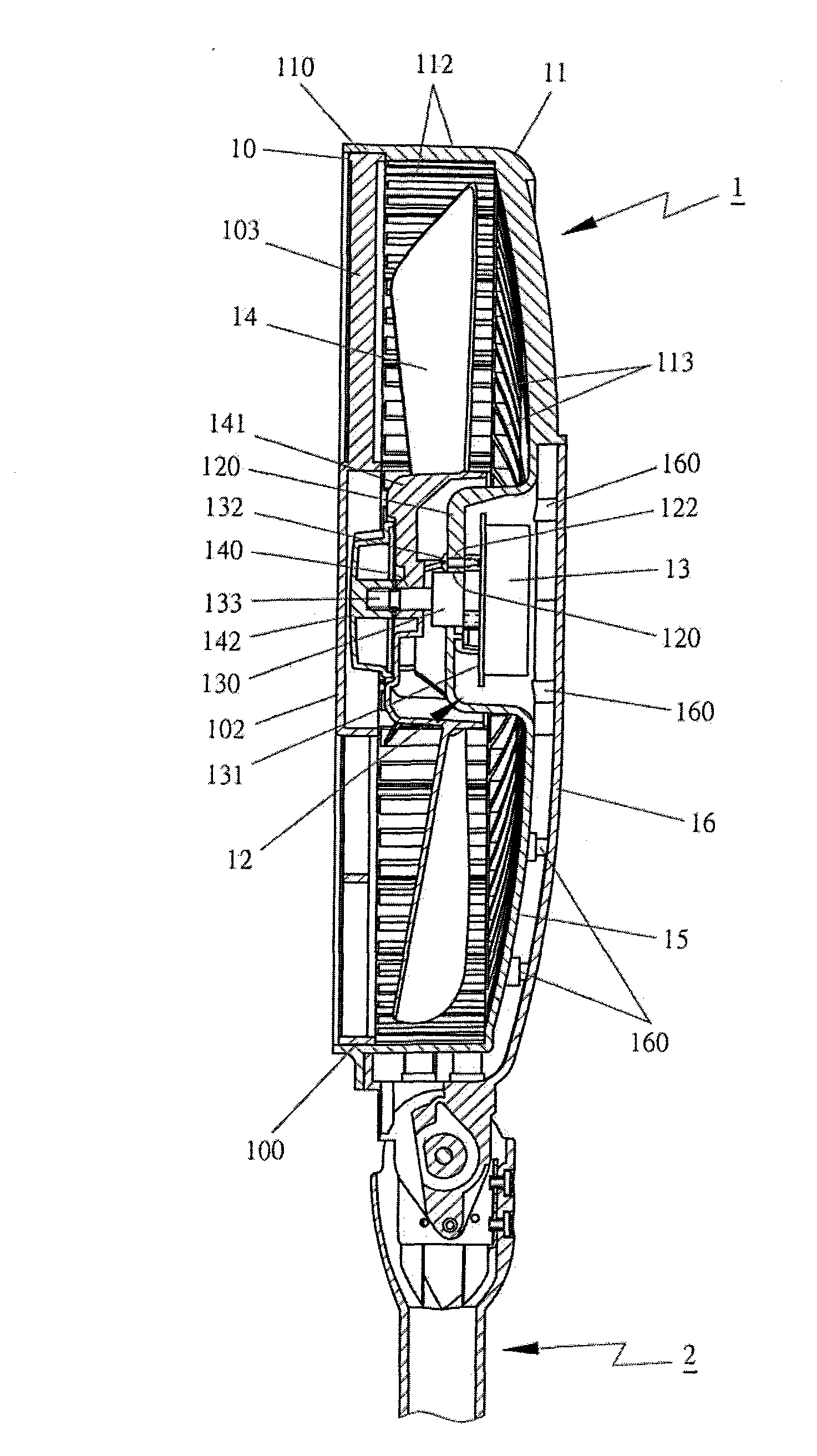
[0033] In this way, in order to enable the public to fully understand the structure of the DC fan described in the present invention, the illustrations are attached as follows:

[0034] Such as figure 1 As shown, the DC electric fan structure of the present invention at least includes three main components: fan body 1 , connecting rod 2 and base 3 . The rear side of the sector 1 is connected with the connecting rod 2 so that the weight of the sector 1 can be supported by the connecting rod 2 . The above-mentioned base 3 has to be set on the ground or on a desktop or above various planes, so that the electric fan can be used more conveniently.

[0035] Such as figure 2 and 3 As shown, the aforementioned fan body 1 is provided with front and rear guard nets 10, 11, the aforementioned front guard net 10 is provided with a surrounding edge 100, and a plurality of engaging holes 101 or engaging grooves are arranged on the aforementioned surrounding edge 100 to match the rear gu...


PUM


Abstract

The invention discloses a direct-current fan structure. The direct-current fan structure at least comprises a fan body provided with a front protection screen and a rear protection screen, wherein an arrangement space for a direct-current motor is formed in the rear protection screen, thus the mandrel of the direct-current motor can be combined with fan blades after being arranged in a penetrating manner, and the fan blades are driven by the direct-current motor to rotate to generate a cool airflow; a connection element is arranged at the rear side of the rear protection screen, the connection element is combined with the upper end of a connection rod, the lower end of the connection rod is combined with a base, and a fixing sleeve is bolted with or separated from the external thread of the connection rod combination portion of the base, that is, the connection rod can be combined with or separated from the base, if the connection rod is separated from the base, the volume of a fan is reduced, and packaging, transport and storage are facilitated.

Description

technical field [0001] The invention relates to the structure of a DC electric fan, in particular to an innovation in the structure of a DC electric fan driven by a DC motor, which saves energy, reduces the high temperature of the motor, and improves the efficiency of the cooling room. Background technique [0002] According to the known electric fan, such as China Taiwan's new patent No. M365987 "improvement of electric fan structure", it is composed of a driving device (10), a fan (20) and a base (30), wherein the driving device (10) includes a housing ( 11) and use the motor (12) driven by AC alternating current 110 volts; the aforementioned housing (11) is equipped with a motor (12), and the aforementioned motor is provided with a rotating shaft (121) to be fixedly connected with the aforementioned fan (20), so that the fan (20) It can be rotated together with the rotating shaft (121) driven by the motor (12); the base (30) includes a base (31) and a bracket (32), so tha...

Claims


Application Information

Patent Timeline
IPC IPC(8): F04D25/08F04D29/00
Inventor 黄进成
Owner 黄进成
Learn More