Flow guide disk of multistage impeller centrifugal pump

A technology of centrifugal pumps and deflectors, which is applied to components, pumps, and pump components of elastic fluid pumping devices, and can solve problems such as increased volume loss, increased water retention time, and hydraulic loss, and achieve lifting work Efficiency and the effect of shortening the residence time

Inactive Publication Date: 2014-10-01
JUNHE PUMPS HLDG
View PDF8 Cites 8 Cited by
  • Summary
  • Abstract
  • Description
  • Claims
  • Application Information

AI Technical Summary

Problems solved by technology

[0003] Due to structural design flaws in the existing deflector, during the entire process of collecting the flow medium flowing out of the pressure relief port of the above-mentioned middle impeller and sending it to the root (inlet) of the next-stage impeller in the pump casing, the water flow is Circulation, mixed flow and other phenomena are prone to occur in the diversion plate, which may easily cause hydraulic loss; at the same time, after the above situation occurs, the residence time of water flow in the diversion plate will inevitably increase, thereby further increasing the volume loss caused by flow leakage
Ultimately, it affects the working efficiency of the multistage impeller centrifugal pump

Method used


Image

  • Flow guide disk of multistage impeller centrifugal pump
  • Flow guide disk of multistage impeller centrifugal pump
  • Flow guide disk of multistage impeller centrifugal pump

Examples


Embodiment 1

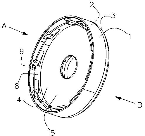
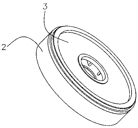
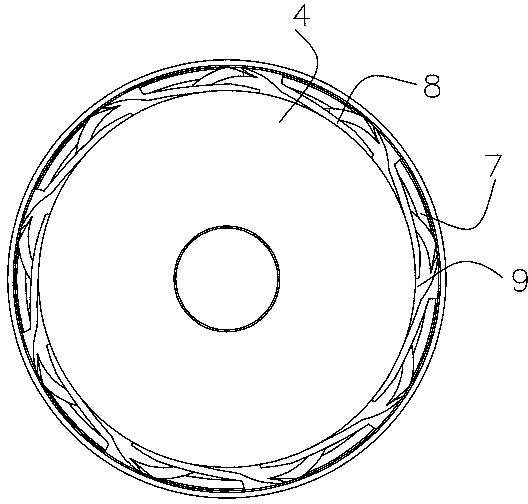
[0018] Such as Figure 1-4 As shown, the guide plate of a multi-stage impeller centrifugal pump provided in this embodiment includes a disc body 1, and the disc body 1 in the above is mainly composed of a disc seat 2 and a disc cover 3, wherein the disc seat 2 is divided into an upper chamber 6 and a lower chamber 5 by a middle partition 4, and a water passage hole 7 passing through the upper chamber 6 and the lower chamber 5 is evenly distributed on the periphery of the middle partition 4, and each Each water passing hole 7 corresponds to a baffle plate 8, the bottom surface of the above-mentioned baffle plate 8 is fixed with the bottom surface of the lower chamber 5 by ultrasonic welding technology, and one end thereof is ultrasonically welded on the inner side wall of the above-mentioned lower chamber 5 and the tangent line at the intersection of the two forms an included angle of 20°, and a water inlet opening 9 is formed between the other end and the adjacent baffle 8, an...


PUM


Abstract

The invention discloses a flow guide disk of a multistage impeller centrifugal pump. A disk base of the flow guide disk is divided into an upper cavity and a lower cavity through a middle partition plate. Water-passing through holes communicated with the upper cavity and the lower cavity are evenly and annularly distributed in the periphery of the middle partition plate. Each water-passing through hole corresponds to a flow baffle. The flow baffles are located on the bottom face of the lower cavity. One end of each flow baffle extends to the inner side wall of the lower cavity, and a water inlet opening is formed between the other end of each flow baffle and the adjacent flow baffle. The flow baffles jointly define an impeller containing cavity. Flow guide ribs are evenly and annularly distributed on the bottom face of the upper cavity, and the space between every two adjacent flow guide ribs corresponds to one water-passing through hole. A disk-covering sealing cover is connected to the edge of the opening of the upper cavity. The flow guide disk solves the technical problem that an existing flow guide disk influences the working efficiency of the multistage impeller centrifugal pump; the working efficiency of the multistage impeller centrifugal pump is guaranteed on the premise of achieving normal operation of the multistage impeller centrifugal pump.

Description

technical field [0001] The invention relates to a deflector of an impeller centrifugal pump, in particular to a deflector of a multistage impeller centrifugal pump. Background technique [0002] The flow guide mechanism in the multistage impeller centrifugal pump structure is mainly composed of impeller and guide plate. When the impeller centrifugal pump is working, the pump shaft drives the impeller to rotate at a high speed. The flow medium (gas and liquid, or a mixture of suspended particles and gas or liquid) enters from the root (inlet) of the impeller, and relies on the high-speed rotation of the impeller to obtain centrifugal force. Throw it to the outer edge of the impeller, and then discharge it from the pressure relief port (outlet) into the guide plate; the function of the guide plate is to collect the flow medium flowing out of the pressure relief port of the above-mentioned middle impeller, and send it to the next stage impeller in the pump casing root (import)...

Claims


Application Information

Patent Timeline
Patent Type & Authority Applications(China)
IPC IPC(8): F04D29/44F04D1/06
CPCF04D29/448F04D1/06
Inventor 张君波
Owner JUNHE PUMPS HLDG
Why Eureka
Try Eureka