Hydraulic pressurizing energy recovery system and control device

A technology for boosting energy and recovering system, applied in the direction of fluid pressure actuating device, fluid pressure actuating system components, fluid pressure converter, etc. The effect of large inertia and hydraulic shock, volume reduction and cost reduction

Inactive Publication Date: 2014-10-01
QINGDAO UNIV
View PDF3 Cites 6 Cited by
  • Summary
  • Abstract
  • Description
  • Claims
  • Application Information

AI Technical Summary

Problems solved by technology

[0002] In the hydraulic system, after the actuators such as hydraulic cylinders and hydraulic motors operate, they usually discharge low-pressure oil, especially in engineering machinery with large potential energy such as excavating machinery, loading machinery and lifting equipment, some of these equipment Actuating components such as excavating arms and booms usually have a large potential energy when they are lowered. This potential energy will prompt the actuators of the hydraulic system to discharge a large amount of low-pressure oil. If the low-pressure oil cannot be fully utilized and directly flows back to the...

Method used


Image

  • Hydraulic pressurizing energy recovery system and control device

Examples


Embodiment Construction

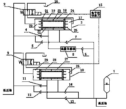
[0024]In the figure, 1. accumulator, 2. first solenoid valve, 3. first hydraulic booster, 4. first check valve, 5. second check valve, 6. third check valve, 7 , the fourth one-way valve, 8, the flow sensor, 9, the second solenoid valve, 10, the second hydraulic booster, 11, the fifth solenoid valve, 12, the sixth solenoid valve, 13, the seventh solenoid valve, 14 , the eighth solenoid valve, 15, the electronic control unit, 16, the oil tank, 17, the low-pressure chamber on the right side of the first hydraulic booster, 18, the high-pressure chamber on the right side of the first hydraulic booster, 19, the first hydraulic booster Left high pressure chamber, 20, left low pressure chamber of the first hydraulic booster, 21, left piston head, 22, piston rod, 23, sub-cavity layer, 24, right piston head, 25, spring, 26, the first Second hydraulic booster right side low-pressure chamber, 27, the second hydraulic booster right side high-pressure chamber, 28, the second hydraulic boost...


PUM


Abstract

Provided are a hydraulic pressurizing energy recovery system and a control device. Two sets hydraulic pressurizing energy recovery systems are provided, the first set hydraulic pressurizing energy recovery system is composed of a first solenoid valve, a first hydraulic pressurizer, a first check valve, a second check valve, a third check valve and a fourth check valve, and the second set hydraulic pressurizing energy recovery system is composed of a second solenoid valve, a second hydraulic pressurizer, a fifth check valve, a sixth check valve, a seventh check valve and an eighth check valve. The control device of each hydraulic pressurizing energy recovery system comprises an electronic control unit and a flow sensor. The rest hydraulic devices comprise an energy accumulator and an oil tank. Low-pressure oil is converted into high-pressure oil through a first pressure amplifier and a second pressure amplifier and is stored in the energy accumulator, and pressurizing energy recovery is completed. According to signals of the flow sensor, the electronic control unit controls the first solenoid valve and the second solenoid valve to be opposite in working position, and controls the first pressure amplifier and the second pressure amplifier to be opposite in moving direction, therefore hydraulic shocking is avoided.

Description

technical field [0001] The invention relates to a hydraulic boosting energy recovery system and a control device, in particular to a device for boosting low-pressure oil in a hydraulic system and collecting energy for the boosted oil. Background technique [0002] In the hydraulic system, after the actuators such as hydraulic cylinders and hydraulic motors operate, they usually discharge low-pressure oil, especially in engineering machinery with large potential energy such as excavating machinery, loading machinery and lifting equipment, some of these equipment Actuating components such as excavating arms and booms usually have a large potential energy when they are lowered. This potential energy will prompt the actuators of the hydraulic system to discharge a large amount of low-pressure oil. If the low-pressure oil cannot be fully utilized and directly flows back to the oil tank, then The energy of these low-pressure oils will be wasted. [0003] In addition, when the rat...

Claims


Application Information

Patent Timeline
IPC IPC(8): F15B3/00F15B21/14
Inventor 张震
Owner QINGDAO UNIV
Why Eureka
Try Eureka