Bidirectional electromagnetic valve

A two-way solenoid valve and one-way valve technology, applied in valve details, valve devices, multi-way valves, etc., can solve the problems of high assembly process cost, failure of check valve core sealing function, complex structure, etc., and achieve assembly process cost Effects of low, easy and efficient assembly, and low processing difficulty

Active Publication Date: 2014-10-01
ZHEJIANG SANHUA COMMERCIAL REFRIGERATION CO LTD
View PDF5 Cites 4 Cited by
  • Summary
  • Abstract
  • Description
  • Claims
  • Application Information

AI Technical Summary

Problems solved by technology

[0018] First, when the electromagnetic valve has a large flow demand, its valve port 1b will increase. Correspondingly, the stroke of the piston 30 needs to increase, and the stroke of the pilot valve head 50 needs to increase synchronously. Correspondingly, the stroke of the moving iron core 40 also needs to increase. However, with the increase of the stroke of the moving iron core 40, the suction force provided by the coil 70 decreases, and the valve opening ability of the valve body 1 drops sharply. In addition, the height of the solenoid valve will also increase; if the coil 70 increases , will bring a series of problems such as high power and temperature rise, and the volume of the solenoid valve will also increase
[0019] Second, during the two-way opening and closing process of the solenoid valve, the first check valve core 30a and the second check valve core 30c must always be aligned with the first piston flow channel 30k and the second piston flow channel 30d, so that radial Otherwise, the sealing function of the two check valve cores will fail, resulting in the failure of the two-way solenoid valve to close or open normally.
As a result, the structure of the pilot valve head 50 is relatively complicated, the processing is difficult, and the assembly process cost is relatively high. Even so, the control accuracy is still not ideal

Method used


Image

  • Bidirectional electromagnetic valve
  • Bidirectional electromagnetic valve
  • Bidirectional electromagnetic valve

Examples


Embodiment Construction

[0071] In order to enable those skilled in the art to better understand the technical solutions of the present invention, the present invention will be further described in detail below with reference to the accompanying drawings and specific embodiments.

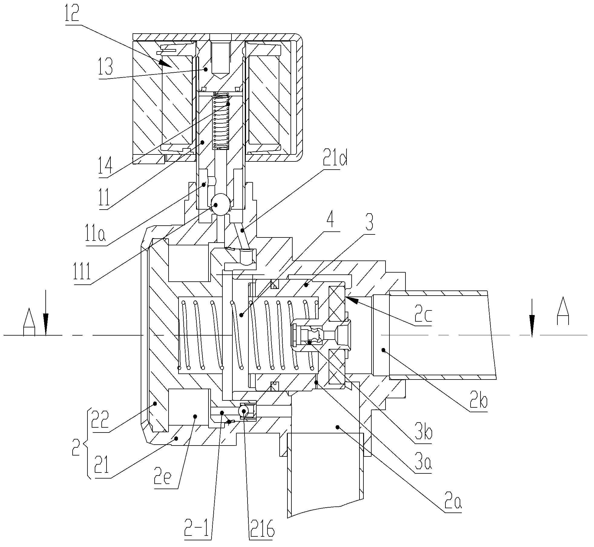
[0072] Please refer to Figure 3-7 , image 3 The axial sectional view of the first embodiment of the linear two-way solenoid valve provided by the invention; Figure 4 for image 3 A-A cross-sectional view; Figure 5 for image 3 Schematic diagram of the middle valve seat; Image 6 for Figure 4 Schematic diagram of the middle valve seat; Figure 7 for image 3 Schematic diagram of the middle valve cover.

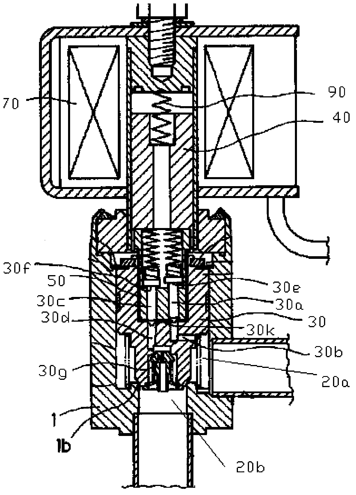
[0073] The two-way solenoid valve has a main valve body 2 and a pilot valve body 11. The valve cavity formed by the main valve body 2 is provided with a piston 3 and forms a piston cavity 4. The main valve body 2 is provided with a first interface 2a and a second interface 2b, the two interfaces are controlled by the axial mo...


PUM


Abstract

The invention discloses a bidirectional electromagnetic valve. A piston is arranged in a valve cavity, and a piston cavity is formed; a first connector and a second connector are arranged on the main valve body; make and break of the first connector and make and break of the second connector are controlled by the piston; the bidirectional electromagnetic valve is also provided with a first flowing channel and a second flowing channel which are respectively connected with the first connector and the second connector, so that refrigerant flows out of the piston cavity; the first flowing channel and the second flowing channel are formed in the main valve body; a pilot valve flowing channel is formed in the main valve body; the piston cavity is connected with a pilot valve opening in a pilot valve body through the pilot valve flowing channel; and a pilot valve head of the pilot valve body moves to open or close the pilot valve opening, so that the first flowing channel and the second flowing channel are connected with or disconnected from the piston cavity. The pilot valve head of the electromagnetic valve is separated from the piston; and when large flow flows through the electromagnetic valve, the stroke of a movable iron core is not required to be increased. The pilot valve head and the main valve body are not easily misplaced, and complicated guiding pieces are not required to be arranged on the main valve body or the pilot valve head. Compared with the background technology, the bidirectional electromagnetic valve has the advantages that the structure is obviously simplified, the machining difficulty and the cost of an assembly process are low, and the control accuracy can meet requirements.

Description

Technical field [0001] The invention relates to the technical field of valve bodies, in particular to a two-way solenoid valve. Background technique [0002] Generally, solenoid valves can only circulate and cut off in one direction due to structural limitations; in conventional systems, they often need to be used in conjunction with check valves. In the heat pump system, the refrigerant flows in the opposite direction during the cooling and heating process, and two single-way solenoid valves need to be installed in series to achieve bidirectional flow. This results in a complicated system structure, low reliability and high cost. Design a two-way solenoid valve. [0003] Please refer to Figure 1-2 , figure 1 It is a schematic diagram of a typical two-way solenoid valve structure, figure 2 for figure 1 Schematic diagram of the structure of the pilot valve head and moving iron core of the two-way solenoid valve. [0004] The two-way solenoid valve is a linear solenoid valve, whic...

Claims


Application Information

Patent Timeline
Patent Type & Authority Applications(China)
IPC IPC(8): F16K11/24
CPCF16K31/406F16K31/06F16K11/24
Inventor 不公告发明人
Owner ZHEJIANG SANHUA COMMERCIAL REFRIGERATION CO LTD
Why Eureka
Try Eureka