
Microwave temperature compensation detector

A technology of temperature compensation and detector, which is applied in the field of microwave technology, can solve the problems of low accuracy and large DC drift of the detection signal, and achieve the effect of small detection voltage temperature drift and small DC temperature drift

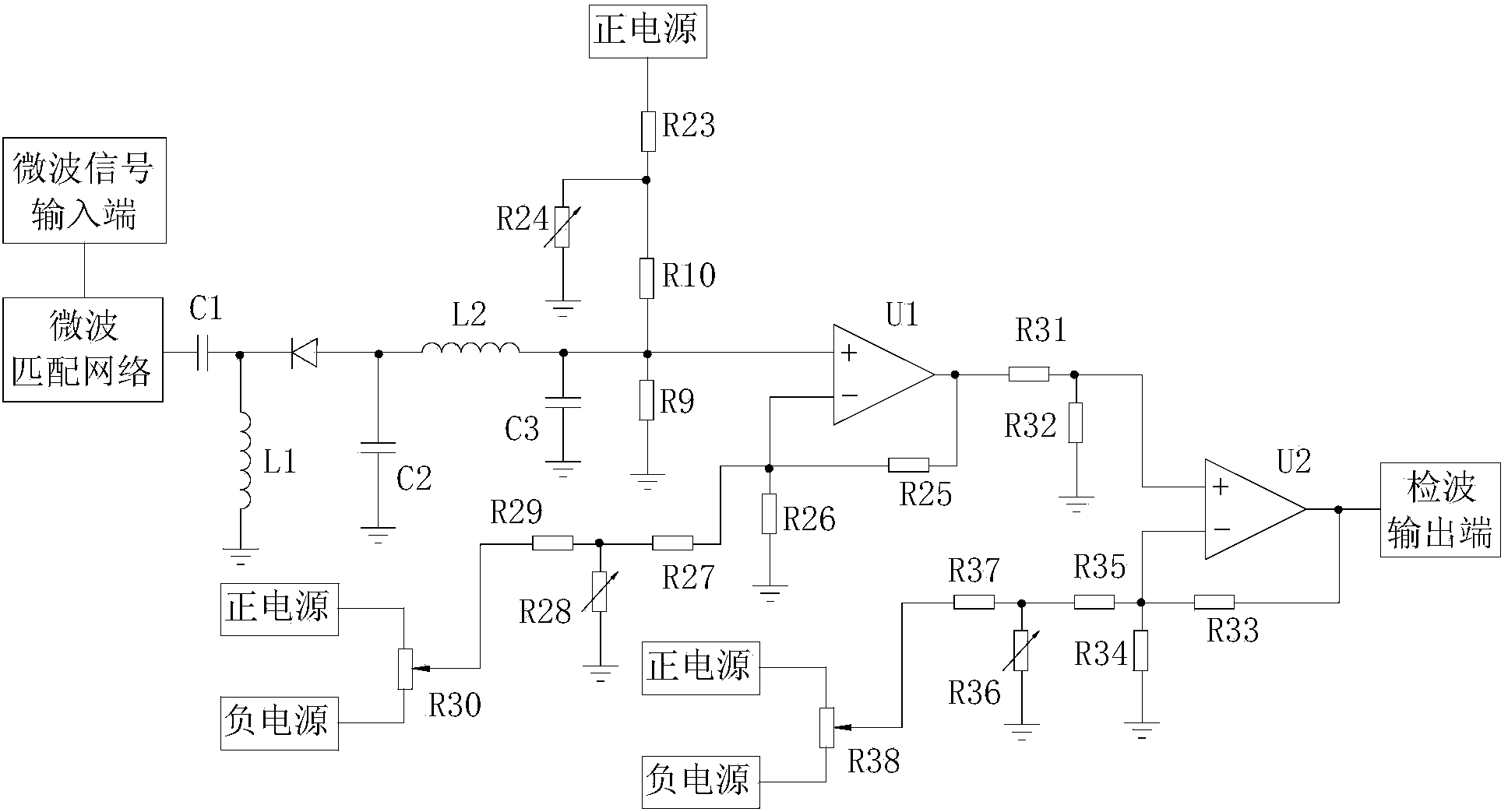
Active Publication Date: 2014-10-01
CHENGDU SINE SCI & TECH
View PDF5 Cites 5 Cited by
  • Summary
  • Abstract
  • Description
  • Claims
  • Application Information

AI Technical Summary

Problems solved by technology

[0010] The purpose of the present invention is to overcome the shortcomings of current diode detectors that are not accurate at different ambient temperatures, the DC drift of the detection signal output is large, and the compensation amount needs to be repeatedly adjusted, and to provide a microwave temperature compensation detector

Method used


Image

  • Microwave temperature compensation detector
  • Microwave temperature compensation detector
  • Microwave temperature compensation detector

Examples


Embodiment

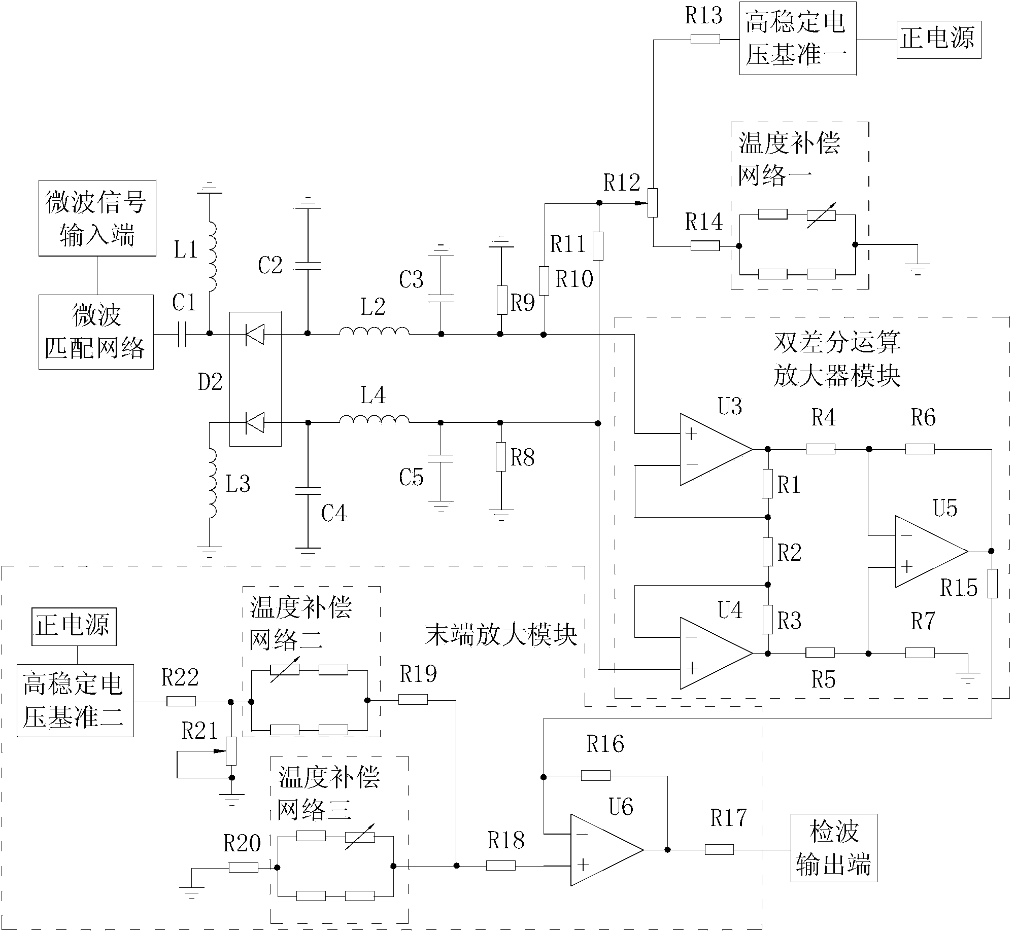
[0028] In this example, the microwave temperature compensation detector can also include a terminal amplification module, and its circuit schematic diagram is as follows image 3 shown.

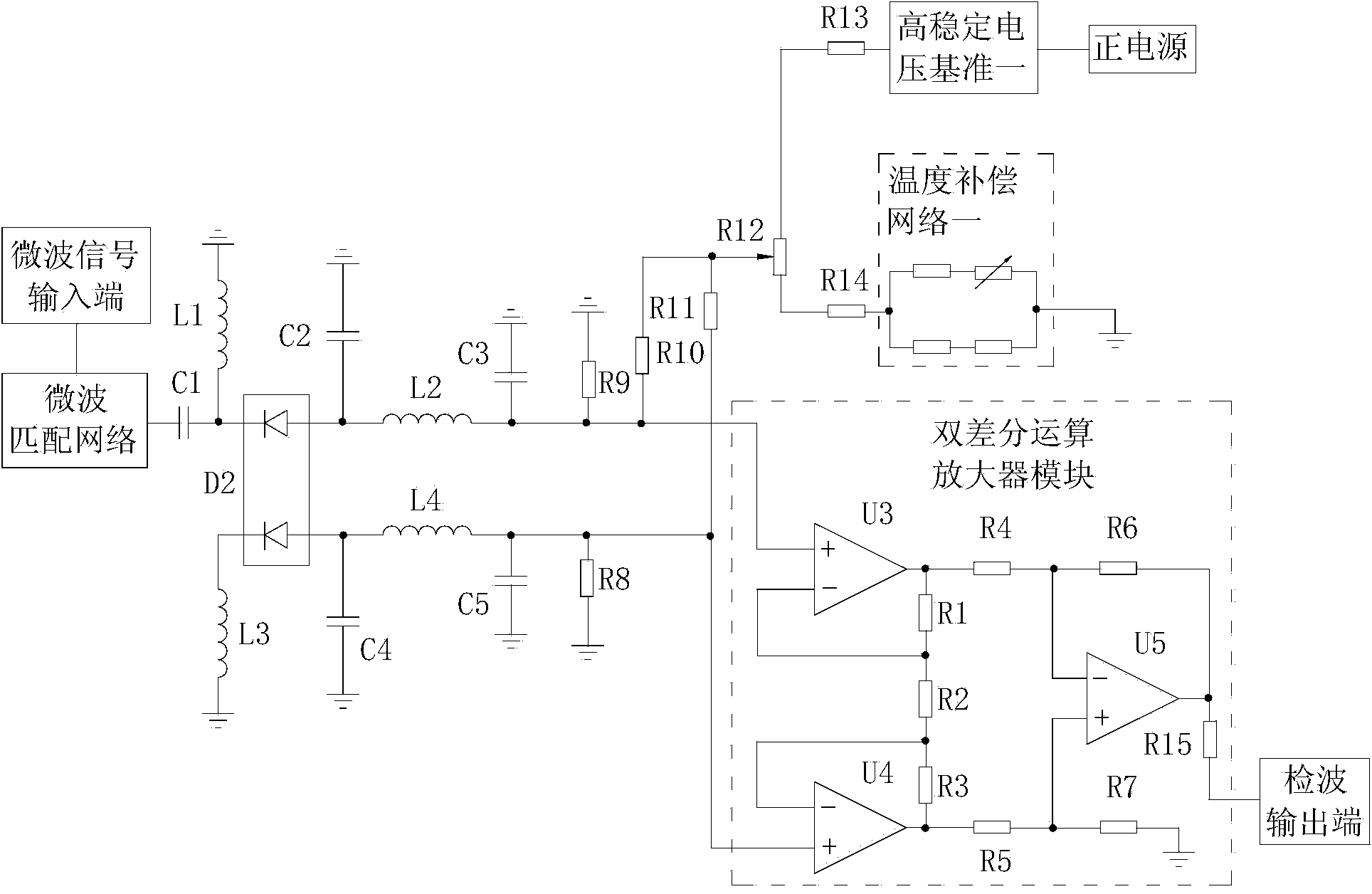
[0029] In the microwave temperature compensation detector of this example, the resistance values ​​of DC bias resistor 1 R8 and DC bias resistor 2 R9 are equal, and the resistance values ​​of DC bias resistor 3 R10 and DC bias resistor 4 R11 are equal. The double differential operation The amplifier module can be made by using a device that integrates two operational amplifiers inside a chip, such as a chip of model AD8672.

[0030] Specifically, the double differential operational amplifier module may include operational amplifier three U3, operational amplifier four U4, resistor one R1, resistor two R2, resistor three R3, resistor four R4, resistor five R5, operational amplifier five U5, resistor six R6, resistor Seven R7 and resistor fifteen R15, the positive phase input terminal of the o...


PUM


Abstract

The invention relates to the microwave technology and discloses a microwave temperature compensation detector. The microwave temperature compensation detector solves the problems that an existing diode detector is low in precision under different environment temperatures, is large in direct current drift of detection signal output and needs to repeatedly debug a compensation dosage. The difference between the microwave temperature compensation detector and the prior art is that the microwave temperature compensation detector uses a double-PN-junction detector diode instead of a detector diode, uses a temperature compensation network instead of a temperature compensation resistor and uses a double-differential operational amplifier module. The microwave temperature compensation detector has beneficial effects of small detector voltage temperature drift and small direct current temperature drift of output.

Description

technical field [0001] The invention relates to microwave technology, in particular to microwave detection technology. Background technique [0002] Signal amplitude is an important parameter that characterizes the characteristics of microwave signals. In recent years, with the rapid development of communication technologies such as digital wireless communication, radar, and radio and television, the frequency range, power level, and modulation of microwave signals used in various modulation techniques The methods and signal spectrum are different. How to choose different detection schemes according to specific applications, so as to realize accurate measurement of microwave signal amplitude, is a problem that electronic test and wireless application researchers must face. [0003] The circuit schematic diagram of the traditional diode detector is as follows: figure 1 As shown, it includes microwave signal input terminal, microstrip matching network, DC blocking capacitor C...

Claims


Application Information

Patent Timeline
Patent Type & Authority Applications(China)
IPC IPC(8): G05F1/567
Inventor 易增辉林洪钢姚宗诚王清文
Owner CHENGDU SINE SCI & TECH
Learn More