
Power supply circuit

A power supply circuit and circuit technology, applied in the electronic field, can solve the problem of burning devices, etc., and achieve the effect of protecting devices and avoiding the generation of reverse current

Inactive Publication Date: 2014-10-01
EMERSON NETWORK POWER ENERGY SYST NORTH AMERICA
View PDF8 Cites 3 Cited by
  • Summary
  • Abstract
  • Description
  • Claims
  • Application Information

AI Technical Summary

Problems solved by technology

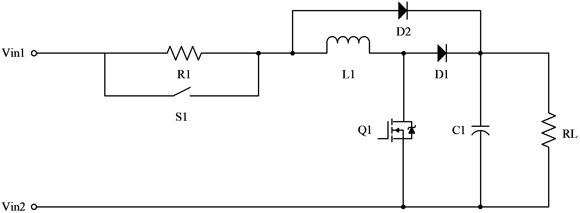
[0003] visible, figure 1 In the circuit shown, the object to be powered has requirements on the polarity of the input power. The voltage Vin1 of the first terminal of the input power must be greater than the voltage Vin2 of the second terminal of the input power. When the user reverses the polarity of the input power by mistake, Or when the AC power is connected by mistake, the voltage Vin1 of the first terminal of the input power will be lower than the voltage Vin2 of the second terminal of the input power, at this time, the diode circuit through the field effect transistor Q1 will form a reverse To the path, a large reverse path current may burn the device on the path

Method used


Image

  • Power supply circuit
  • Power supply circuit
  • Power supply circuit

Examples


Embodiment 1

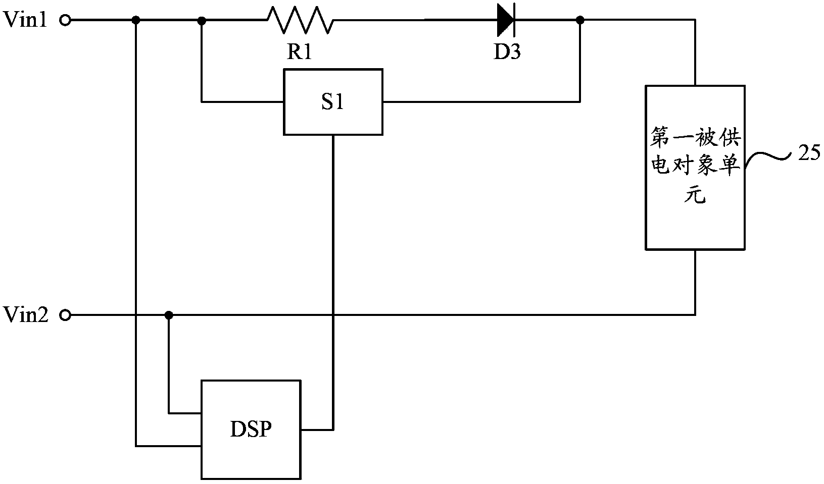
[0033] The detailed structure of the power supply circuit provided by Embodiment 1 of the present invention is as follows image 3 As shown, it includes resistor R1, diode D3, normally open switch S1, DSP and the first powered object unit 25, wherein:

[0034] One end of the resistor R1 and the diode D3 connected in series is the first terminal Vin1 of the input power supply, and the other end is connected to the first end of the first powered object unit 25; the second end of the first powered object unit 25 is the second terminal of the input power supply. Two terminals Vin2; the first terminal of the normally open switch S1 is the first terminal Vin1 of the input power supply, and the second terminal is connected to the first terminal of the first powered object unit 25; the two signal input terminals of the DSP are respectively the input power supply Two connection terminals Vin1 and Vin2, one signal output terminal is connected to the third terminal of the normally open s...

Embodiment 2

[0055] The detailed structure of the power supply circuit provided by Embodiment 2 of the present invention is as follows Figure 6 As shown, it includes resistor R1, first normally open switch S1, second normally open switch S2, DSP and second powered object unit 55, wherein:

[0056] One end of the resistor R1 and the second normally open switch S2 connected in series is the first terminal Vin1 of the input power supply, and the other end is connected to the first end of the second powered object unit 55; the second end of the second powered object unit 55 is The second terminal Vin2 of the input power supply; the first terminal of the first normally open switch S1 is the first terminal Vin1 of the input power supply, and the second terminal is connected to the first terminal of the second powered object unit 55; the two signals of the DSP The input terminals are respectively two terminals Vin1 and Vin2 of the input power supply, and the two signal output terminals are conne...


PUM


Abstract

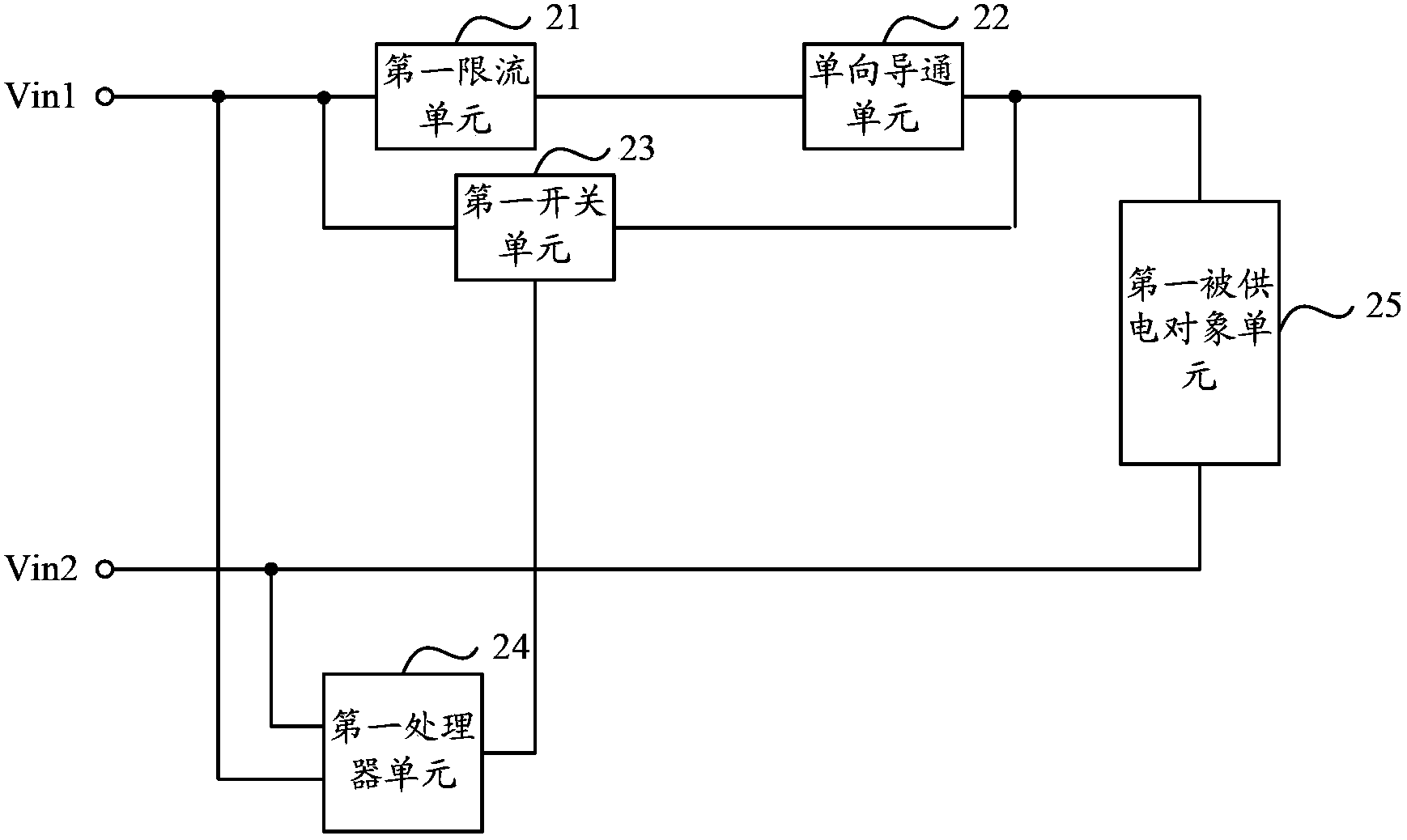
The invention discloses a power supply circuit which comprises a first current limiting unit, a one-way conduction unit, a first switch unit, a first processor unit and a first power supply object unit. One end of the first current limiting unit which is connected with the one-way conduction unit in series is a first wiring terminal of an input power supply while the other end is connected with a first end of the first powered object unit; a second end of the first power supply object unit is a second wiring terminal of the input power supply; a first end of the first switch unit is the first terminal of the input power supply and a second end of the first switch unit is connected with the first end of the first power supply object unit; two signal input ends of the first processor unit are the two wiring terminals of the input power supply respectively and a signal output end of the first processor unit is connected with a third end of the first switch unit. The power supply circuit can protect a circuit device.

Description

technical field [0001] The invention relates to the field of electronic technology, in particular to a power supply circuit. Background technique [0002] In current power supply circuits, slow start is often used to avoid power-on shocks to the objects to be powered. The object to be powered may be a power-consuming load, or may be a specific circuit, such as a DC / DC converter such as a Boost converter or a Buck converter. Taking the Boost converter as an example to be powered, the slow start power supply circuit in the prior art will be described below, as figure 1 As shown, the Boost converter is composed of the first diode D1, the second diode D2, the inductor L1, the capacitor C1 and the field effect transistor Q1. The Boost converter boosts the input power and outputs it to the load RL. The resistor The slow start unit composed of R1 and normally open switch S1 can realize the slow start when the circuit is powered on. [0003] visible, figure 1 In the circuit show...

Claims


Application Information

Patent Timeline
IPC IPC(8): H02M3/155H02H11/00
Inventor 刘兆元柳树渡刘韧李清纯
Owner EMERSON NETWORK POWER ENERGY SYST NORTH AMERICA
Learn More