Prosthesis component

A technology of prosthesis and components, applied in the direction of prosthesis, medical science, hip joint, etc., can solve the problem of reducing the available space of the femoral head

Active Publication Date: 2014-10-01
BIOMET UK HEALTHCARE
View PDF10 Cites 3 Cited by
  • Summary
  • Abstract
  • Description
  • Claims
  • Application Information

AI Technical Summary

Problems solved by technology

[0006] However, the inclusion of additional liners reduces the space available to the femoral head, meaning that additional fixation comes at the expense of a reduced range of motion

Method used


Image

  • Prosthesis component
  • Prosthesis component
  • Prosthesis component

Examples


Embodiment Construction

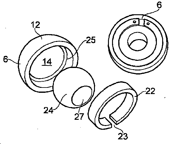
[0036] The present invention relates to a dual mobility acetabular prosthetic component and mating femoral head prosthetic component which together provide a hip prosthesis with ceramic-to-ceramic and ceramic-to-carbon fiber reinforced polymer articulation.

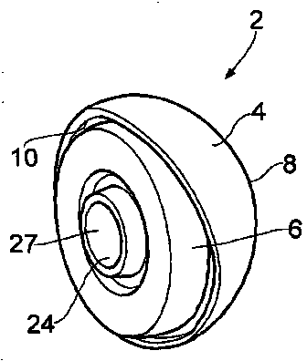
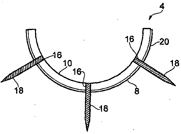
[0037] refer to figure 1 and 2 , according to an embodiment of the present invention, the acetabular prosthesis assembly 2 includes a shell 4 and a liner 6 . The shell 4 is substantially hemispherical and formed from a carbon fiber reinforced polymer material. According to the embodiment of the invention described below, the housing 4 is formed from carbon fiber reinforced polyether ether ketone (CFR-PEEK), however, it will be appreciated that other fiber reinforced polymer materials are contemplated. Carbon fiber-reinforced polymer materials, such as CFR-PEEK, provide low-wear bearing surfaces, which also offer an alternative to metal bearing surfaces, considering the adverse effects already documented in the literatur...


PUM


Abstract

A prosthesis component (2) is disclosed, the component comprising a shell (2) formed form a carbon fibre reinforced polymer material and having an inner bearing surface (10); and a liner (6) formed from a ceramic material and having an outer bearing surface(12); wherein the liner (6) is received in an articulating manner within the shell (4). A hip replacement prosthesis is also disclosed, the hip replacement prosthesis comprising a prosthesis component (2) as disclosed and a femoral head prosthesis component (24), the femoral head prosthesis component being formed from a ceramic material.

Description

technical field [0001] The invention relates to a prosthesis assembly, in particular to a prosthesis assembly with a shell and a hinged liner. Background technique [0002] It is known to replace damaged or damaged natural bone joints with prosthetic components. For example, a natural hip joint that has degenerated can be replaced with an artificial joint consisting of a prosthetic acetabular component implanted in the patient's acetabulum and a prosthetic femoral head component implanted in the patient's femur to articulate with the prosthetic acetabular component . This type of artificial component is called a total hip replacement (THR). [0003] Various types of THR exist and are known in the art. These different types of prostheses take different approaches to balancing the competing demands of reducing joint wear, maintaining joint stability, increasing the patient's range of motion, and many other aspects. Reducing wear and tear on prosthetic components can be ach...

Claims


Application Information

Patent Timeline
Patent Type & Authority Applications(China)
IPC IPC(8): A61F2/34
CPCA61F2002/3401A61F2/30965A61F2002/3233A61F2/34A61F2/32A61F2002/3275A61F2002/3208A61F2002/325A61F2002/3241A61L27/18
Inventor 罗伯特-约翰-安德鲁·比格斯比穆罕默德-伊姆兰·科汗(博士)
Owner BIOMET UK HEALTHCARE
Why Eureka
Try Eureka