

Position detection device
A technology for detection devices and detection parts, which is applied in printing devices, focusing devices, projection devices, etc., can solve problems such as poor image quality, high power consumption, and long imaging time, so as to shorten the time spent and reduce power consumption volume effect
- Summary
- Abstract
- Description
- Claims
- Application Information
AI Technical Summary
Problems solved by technology
Method used
Image

Examples
Embodiment approach 1
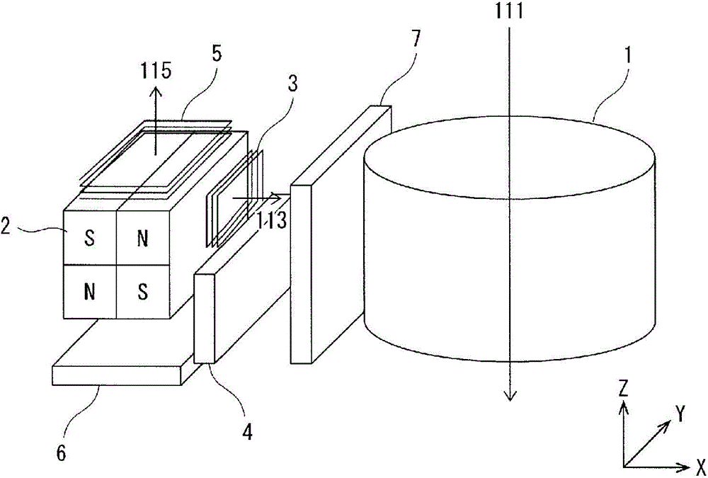
[0072] figure 1 It is a figure which shows an example of Embodiment 1 of the position detection apparatus of this invention for demonstrating. Reference numeral 1 in the drawing denotes a lens, reference numeral 2 denotes a permanent magnet (magnet for X-axis OIS and AF magnet), reference numeral 3 denotes a coil for autofocus (AF), and reference numeral 4 denotes a position for AF Sensor (Hall element), reference numeral 5 denotes a coil for X-axis OIS, reference numeral 6 denotes a position sensor (Hall element) for X-axis OIS, reference numeral 111 denotes an optical axis of a lens, and reference numeral 113 denotes The axis direction of the coil for autofocus (AF), reference numeral 115 denotes the axis direction of the coil for X-axis OIS.
[0073] The position detection device of the present invention is a position detection device that detects the position of the lens 1 in a plane perpendicular to the optical axis direction of the lens 1 to detect the position for sha...
Embodiment approach 2
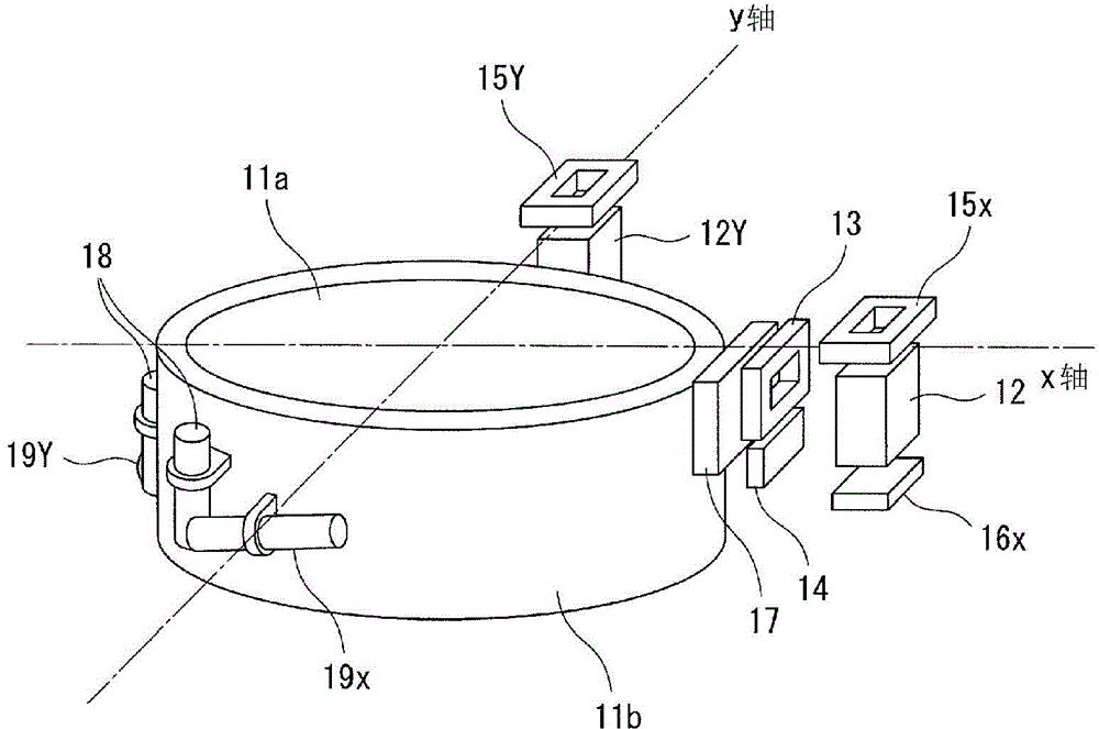
[0133] Figure 10 (a), Figure 10 (b) is a configuration diagram for explaining Embodiment 2 of the position detecting device of the present invention, Figure 10 (a) is a plan view, Figure 10 (b) is a bottom view. Reference numeral 31 in the figure denotes an elastic member (spring (Japanese: bane or springing)), and reference numeral 32 denotes a support (power supply terminal). Additionally, pairs with figure 2 and image 3 Component elements with the same function are marked with the same reference signs.
[0134] Such as Figure 10 (a), Figure 10 As shown in (b), it includes: a driving body 11b, which holds the lens 11a; four pillars 32, which are arranged at the four corners in the housing 21, as power supply terminals for supplying driving current; The pillars 32 are two spring members (springs (Japanese: バネ or springing)) each connected to the drive body 11b. Moreover, the drive body 11b is comprised from the lens barrel (1st drive body) 11b1, and the 2nd d...
Embodiment approach 3
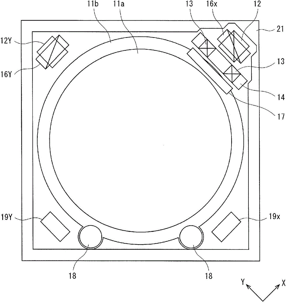
[0168] Figure 22 It is a perspective view for explaining Embodiment 3 of the position detecting device of the present invention, Figure 23 yes Figure 22 The shown plan view of the position detection device is a view of the position detection device viewed from the direction of the optical axis a of the lens. Reference numeral 12A in the figure denotes a permanent magnet (magnet for A-axis OIS and AF magnet), reference numeral 12B denotes a magnet for B-axis OIS, reference numeral 13 denotes a coil for autofocus (AF), and reference numeral 14 Denotes a Hall element for AF, reference numeral 15A denotes a coil for A-axis OIS (shake correction), reference numeral 15B denotes a coil for B-axis OIS, reference numeral 16A denotes a Hall element for A-axis OIS, and reference numeral 16B Denotes a Hall element for B-axis OIS, reference numeral 17 denotes a yoke, reference numeral 18 denotes a shaft for AF drive, reference numeral 19A denotes a drive shaft for A-axis OIS, and refe...
PUM
 Abstract
Description
Claims
Application Information