High-efficiency self-cooled reamer

A self-cooling, reamer technology, applied in reamers, metal processing equipment, manufacturing tools, etc., can solve the problems of lack of cooling effect, force, resistance, and lower hardness of the cutter head, etc., to improve the heat dissipation effect , prolong the service life, reduce the effect of cutting temperature

Inactive Publication Date: 2014-10-08
李仕清
View PDF6 Cites 2 Cited by
  • Summary
  • Abstract
  • Description
  • Claims
  • Application Information

AI Technical Summary

Problems solved by technology

[0002] At present, the reamers used in mechanical processing are composed of chamfering edge, auxiliary cutting edge, cutting surface, auxiliary cutting surface, and cutting edge. The cutting edge is roughly in a single cutting force mode, that is, although each reamer has multiple , each cutting strip has a complete cutting edge. The cutting edge of this structure, especially the tapered reamer, has a large overall force and resistance. Especially when reaming a workpiece with high hardness, a large amount of heat is generated, resulting in The hardness of the cutting head is reduced, resulting in the wear of the cutting head, and the cooling technology becomes the bottleneck of the use of the cutting tool. It is difficult to directly inject the coolant into the cutting part with ordinary technology, and the ideal cooling effect cannot be achieved.

Method used


Image

  • High-efficiency self-cooled reamer
  • High-efficiency self-cooled reamer
  • High-efficiency self-cooled reamer

Examples


Embodiment approach 1

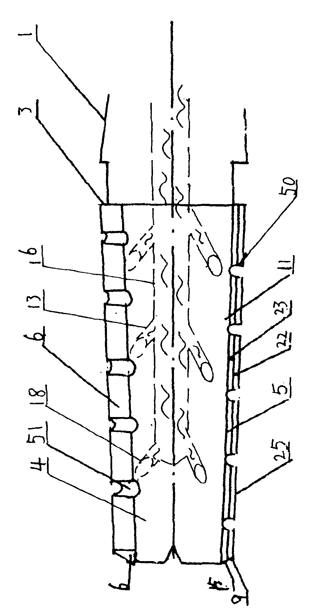
[0023] Such as figure 1 , Figure 5-Figure 8 As shown, the high-efficiency self-cooling reamer of the first embodiment of the present invention is specifically a hand reamer or a machine reamer or an adjustable or combined or solid carbide or welded or integrated or other reamer The cutting edge 8 or the chamfering edge 9 or the reamer whose cutting edge 8 is a straight edge or a tapered edge or a blade includes a tool handle 1 and a tool head 2, the tool handle 1 and the tool head 2 are connected or formed as one, and the tool head 2. A plurality of cutting blades or cutting bars 3 are integrally provided, and each cutting blade or cutting bar 3 has a cutting surface 11, and the axial front portion of the cutting surface 11 is chamfered to form a chamfered surface, The rear side of the cutting surface 11 facing the cutting direction is the rear cutting surface 4, the surface outside the top of the cutting surface 11 is the minor cutting surface 6, the cutting surface 11 inte...

Embodiment approach 2

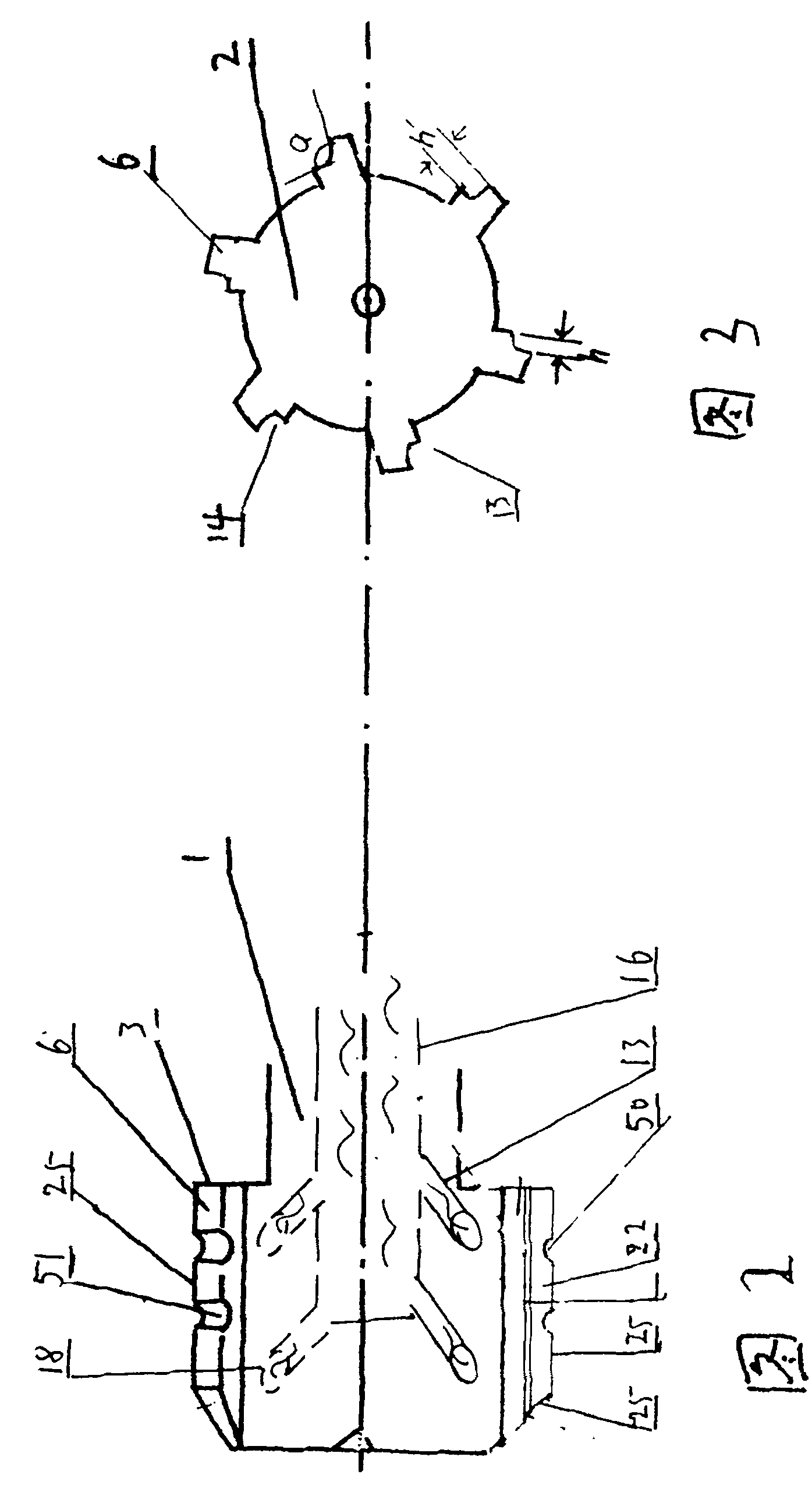
[0028] Such as Figure 2-3 , Figure 5-Figure 8 As shown, the embodiment of the self-cooling reamer of the second embodiment of the present invention is based on the first embodiment. In this embodiment, a notch edge 20 is provided on the main cutting edge 21, and the notch edge 20 is directed to The cutting surface 7 extends to form a groove 19, and the setting of the notch edge 20 is applied to a reamer with a relatively short edge of the tool head, and the implementation effect is the same as that of the first embodiment.

Embodiment approach 3

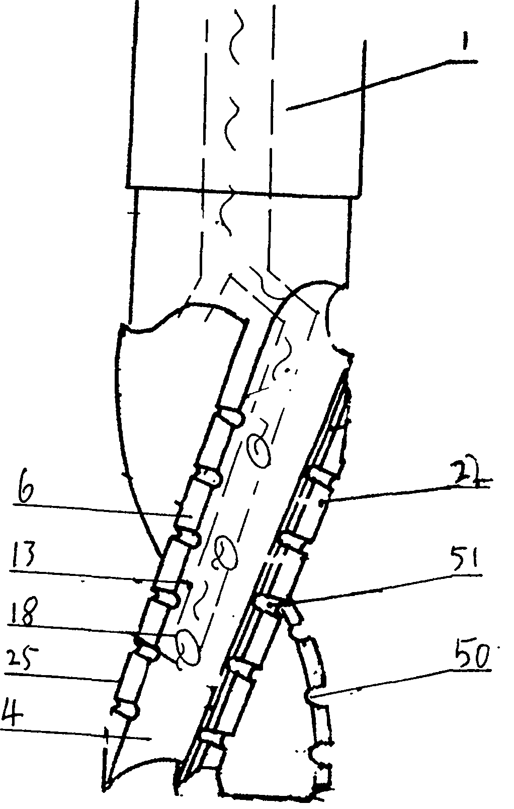
[0030] Such as Figure 4 , Figure 5-Figure 8 As shown, the embodiment of the self-cooling reamer of the third embodiment of the present invention, on the basis of the first - second embodiment, this embodiment is to apply the above technology to the spiral reamer, the implementation effect and implementation Method 1 has the same result.

[0031] According to the above structure, it has been proved that the effect of cooling the tool from the cutting place by the coolant is far greater than that achieved by flowing downward from the top. On the one hand, the waste chips cut by the tool also prevent the coolant from reaching the cutting place effectively, but the way of sending the coolant directly to the cutting place through the cooling pipe does not have the above defects, so the waste chips can be effectively pushed out and the auxiliary cutting is reduced. The frictional strength of the blade reduces the amount of frictional heat generated, reduces the temperature of th...


PUM


Abstract

The invention provides a high-efficiency self-cooled reamer, and mainly relates to a center bit or a countersink bit for machining. The high-efficiency self-cooled reamer is characterized in that a cutting edge is arranged on each spiral strip of the reamer; a cutting surface is formed along the outer side of the cutting edge; the cutting surface is arranged on the front part of the cutting edge facing to the cutting direction; cooling holes or cooling troughs are formed in the axial center of the reamer and nearby; the lower ends of the cooling holes or the cooling troughs are communicated with cooling ports in grooves in the front parts of the cutting surfaces of the center bit or the countersink bit; the upper end of the center bit or the countersink bit is communicated with an integrally-formed cooling pipe on a handle part of the center bit or the countersink bit; connecting ports are formed on a handle body or at the front end of the axial center of the handle part of the center bit or the countersink bit.

Description

Technical field: [0001] The invention relates to a high-efficiency self-cooling reamer, which is used in the reaming process in machining. Background technique: [0002] At present, the reamers used in mechanical processing are composed of chamfering edge, auxiliary cutting edge, cutting surface, auxiliary cutting surface, and cutting edge. The cutting edge is roughly in a single cutting force mode, that is, although each reamer has multiple , each cutting strip has a complete cutting edge. The cutting edge of this structure, especially the tapered reamer, has a large overall force and resistance. Especially when reaming a workpiece with high hardness, a large amount of heat is generated, resulting in The hardness of the cutting head is reduced, resulting in the wear of the cutting head, and the cooling technology becomes the bottleneck of the use of the cutting tool. It is difficult to inject the coolant directly into the cutting part with ordinary technology, and the ideal...

Claims


Application Information

Patent Timeline
IPC IPC(8): B23D77/00
Inventor 李仕清
Owner 李仕清
Why Eureka
Try Eureka