Gas filling bottle welding rotating device and working method thereof

A technology for rotating devices and filling bottles, applied in auxiliary devices, welding equipment, welding equipment, etc., can solve the problems of restricting production efficiency and production quality, increasing labor costs for skilled workers, increasing factory production costs, etc., and achieve simple and convenient control , reduce the requirements for input and proficiency, and achieve high production efficiency

Active Publication Date: 2014-10-08
无锡市迪索数控焊接设备有限公司
View PDF7 Cites 4 Cited by
  • Summary
  • Abstract
  • Description
  • Claims
  • Application Information

AI Technical Summary

Problems solved by technology

[0003] In production practice, it is found that girth welding is the bottleneck of the entire manufacturing process. On the one hand, there are too many human factors in the current tooling and welding methods, and the fluctuation of workers' operation le

Method used


Image

  • Gas filling bottle welding rotating device and working method thereof
  • Gas filling bottle welding rotating device and working method thereof
  • Gas filling bottle welding rotating device and working method thereof

Examples


Example Embodiment

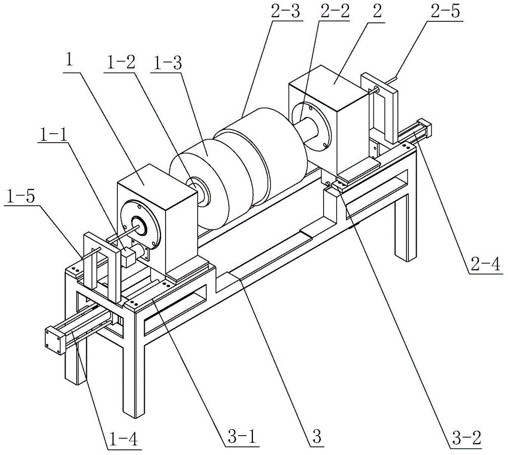
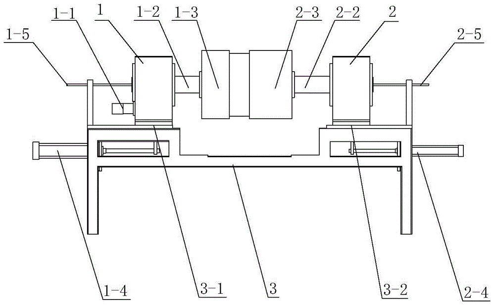
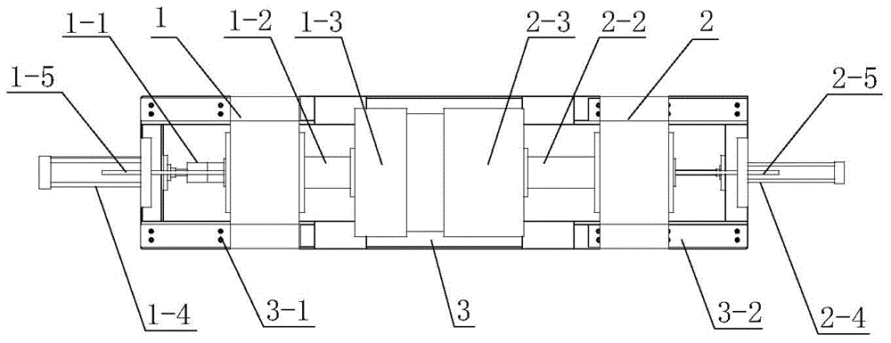
[0024] Embodiment: The gas filling bottle welding rotating device of this embodiment is used to clamp the gas filling bottle during automatic welding, and its overall structure is as follows figure 1 , figure 2 with image 3 As shown, it includes an active rotating body 1 and a driven rotating body 2 symmetrically arranged on the frame 3. The active rotating body 1 has an active motor 1-1 and an active rotating shaft 1-2 engaged with each other. The end of the active rotating shaft 1-2 is equipped with a first jacket 1-3 that matches the outer contour of one end of the gas filling bottle. . The driven rotating body 2 has a driven rotating shaft 2-2 on the same line as the driving rotating shaft 1-2, and a second clamp for holding the other end of the gas filling bottle is installed at the end of the driven rotating shaft 2-2 The inner wall of the second jacket 2-3 matches the outer contour of the other end of the gas filling bottle.

[0025] The frame 3 has a first guide rail ...


PUM


Abstract

The invention discloses a gas filling bottle welding rotating device and a working method thereof. The device comprises a machine frame, a driving rotating body, a driven rotating body, clamping sleeves and a motor and the like, wherein the driving rotating body and the driven rotating body can move relatively, and the clamping sleeves are installed on the driving rotating body and the driven rotating body. The working method of the gas filling bottle welding rotating device comprises the steps of feeding, clamping, rotation and blanking and the like. The gas filling bottle welding rotating device can greatly improve gas filling bottle production efficiency and reduce manpower resource investment.

Description

technical field [0001] The invention relates to an automatic welding device, in particular to a gas filling bottle welding rotary device and a working method thereof. Background technique [0002] Gas filling bottle is a commonly used pressure container, which is often used to store combustible gas. It has strict requirements on airtightness and structural strength, which also puts forward higher requirements for its manufacturing process. The manufacturing process of a common liquefied petroleum gas cylinder is as follows: two half-shells are stamped and formed, butt joint welding ring seam, assembly of bottle mouth parts and inspection. For the welding of the circular seam, semi-automatic welding tooling is currently used, such as the liquefied petroleum gas cylinder circular seam welding device disclosed in the Chinese patent document CN201900395U, that is, manual loading, and the workpiece is clamped by the tooling fixture and then rotated. For circular seam welding, ma...

Claims


Application Information

Patent Timeline
IPC IPC(8): B23K9/022B23K9/028B23K9/12B23K9/28B23K37/00B23K37/053
CPCB23K37/053B23K2101/12
Inventor 周辰
Owner 无锡市迪索数控焊接设备有限公司
Why Eureka
Try Eureka