
Cooling device welded between subsea valve and transition pipe

A technology of cooling device and transition pipe, which is applied in the direction of auxiliary devices, welding equipment, auxiliary welding equipment, etc., can solve the problems of insignificant spray cooling effect, limited on-site operation, and affecting the performance of valve products, etc.

Active Publication Date: 2016-02-24
CHINA NAT OFFSHORE OIL CORP +2
View PDF6 Cites 0 Cited by
  • Summary
  • Abstract
  • Description
  • Claims
  • Application Information

AI Technical Summary

Problems solved by technology

Due to the inconspicuous effect of air cooling and water spray cooling or the limited on-site operation and no cooling measures, this welding process will cause thermal damage to the valve and affect the performance of the valve product.

Method used


Image

  • Cooling device welded between subsea valve and transition pipe

Examples


Embodiment Construction

[0020] The present invention will be further described below in conjunction with the accompanying drawings, but the present invention is not limited to the following embodiments.

[0021] In marine underwater oil and gas, petroleum (petroleum and natural gas) exploitation and production devices, underwater valves and underwater actuator devices are used. The connection between underwater valves and various underwater production devices can be flanged (water depth less than 300 meters) or welded connections (water depth greater than 300 meters). For valve devices that adopt welded connections, they must be connected, assembled and debugged on land before they can be launched into the water. In the land welding process, the underwater valve device needs to be welded with the transition pipe and the valve welding end before leaving the factory, and then it can be welded and assembled with other devices before leaving the factory.

[0022] In the underwater valve manufacturing pl...


PUM


Abstract

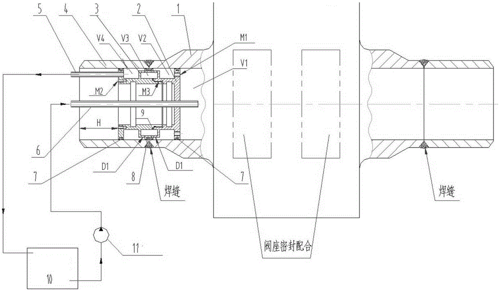
The invention discloses a cooling device for welding between an underwater valve and a transition tube. According to the cooling device, an annular labyrinth channel is placed in a valve of a welding area to form a cooling fluid sealed circulating path. Heat of the welding area is circularly carried by cooling fluid, welding heat conducted to the valve is reduced, and damage of high temperature to parts of the valve is reduced in the welding process. According to the device, the flow and the flow speed of the cooling fluid can be adjusted through external control equipment, and control of the cooling effect is achieved. Tap water or the cooling fluid is injected into a fluid channel through a circulating pump and a water inlet pipe, and then the tap water or the cooling fluid is discharged into a cooling fluid circulating box through the labyrinth channel in the cooling device, and the labyrinth channel is formed by sequentially communicating an annular cavity I, an annular cavity II and an annular cavity III. Heat is circulated and exchanged, the aim of cooling the metal valve is achieved, and it is guaranteed that heat conduction cannot damage sealing parts in the valve.

Description

technical field [0001] The invention relates to a cooling device welded between an underwater valve and a transition pipe, belonging to the field of deep sea control valves. Background technique [0002] my country's offshore oil and gas exploration and development started late, lacking key technologies and equipment for offshore oil underwater equipment with independent intellectual property rights, and basically relying on imports. With the strategic transfer of my country's oil exploration and development to the ocean, the demand for offshore oil equipment is further increased, and the dependence on foreign technology and equipment is greater. Therefore, whether it is from the perspective of national energy security or the future development of the equipment manufacturing industry Therefore, it is imminent to develop drilling and production equipment suitable for my country's oil and gas exploration and development. [0003] The underwater valve device technology and equi...

Claims


Application Information

Patent Timeline
Patent Type & Authority Patents(China)
IPC IPC(8): B23K37/00
CPCB23K37/003
Inventor 闫嘉钰刘少波洪毅郭宏孙钦马玉山高强常占东
Owner CHINA NAT OFFSHORE OIL CORP
Learn More