Eureka AIR delivers breakthrough ideas for toughest innovation challenges, trusted by R&D personnel around the world.

Cable bridge wall-following horizontal installing mechanism

A cable tray and installation mechanism technology, applied in electrical components, mechanical equipment, fixtures, etc., can solve the problems of easy corrosion, shortened life of cover plates and brackets, easy to rust, etc., and achieve strong corrosion resistance and stability. Good, firm and reliable installation

Inactive Publication Date: 2014-10-08
ZHENJIANG JIANGDAO ELECTRICAL MFG
View PDF5 Cites 1 Cited by
  • Summary
  • Abstract
  • Description
  • Claims
  • Application Information

AI Technical Summary

Problems solved by technology

The horizontal installation mechanism of cable tray along the wall is also a common application, but the cover plate and bracket in the original horizontal installation mechanism of cable tray along the wall are generally made of iron sheet and cast iron respectively. The finished cover plate and the bracket made of cast iron have the disadvantages of being easy to corrode and rust, which will shorten the life of the cover plate and bracket, resulting in the need to replace the cover plate and bracket, thus Increased working time and costs
[0003] In addition, the original cable bridge horizontal installation mechanism along the wall does not adopt the splint fixing method, so it has the disadvantage that the fixed installation is not stable enough

Method used


Image

  • Cable bridge wall-following horizontal installing mechanism

Examples


Embodiment Construction

[0016] The preferred embodiments of the present invention will be described in detail below in conjunction with the accompanying drawings, so that the advantages and features of the present invention can be more easily understood by those skilled in the art, so as to define the protection scope of the present invention more clearly.

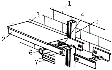
[0017] Such as figure 1 As shown, a cable bridge horizontal installation mechanism along the wall includes a wall 1, a cable bridge 2, a cover plate 3, a plywood 4, a channel steel 5, a bracket 6, and a connecting piece 7, and the wall 1 is fixedly installed with a channel steel 5. A bracket 6 is installed on the channel steel 5, a connecting piece 7 is arranged on the bracket 6, a cable bridge 2 is installed on the upper end of the bracket 6, and a cover plate 3 is installed on the upper end of the cable bridge 2, The bracket 6 is also provided with a splint 4, the splint 4 is used to fix and clamp the cable tray 2, the cover plate 3 is made of ...


PUM


Abstract

The invention provides a cable bridge wall-following horizontal installing mechanism which comprises a wall (1), a cable bridge (2), a cover plate (3), a clamp plate (4), channel steel (5), a bracket (6) and a connecting piece (7). The cable bridge wall-following horizontal installing mechanism is characterized in that the channel steel (5) is fixedly installed on the wall (1), the bracket (6) is installed on the channel steel (5), the connecting piece (7) is arranged on the bracket (6), the cable bridge (2) is installed at the upper end of the bracket (6), the cover plate (3) is installed at the upper end of the cable bridge (2), and the clamp plate (4) is further arranged on the bracket (6) and used for fixing and clamping the cable bridge (2). The cover plate and the bracket on the cable bridge wall-following horizontal installing mechanism are respectively made of stainless steel and aluminum alloy, and the corrosion resistance is good. In addition, the cable bridge is fixed and clamped by adopting the clamp plate, and the cable bridge wall-following horizontal installing mechanism has the advantages of being firm and reliable in installation and good in stability.

Description

technical field [0001] The invention relates to an installation mechanism, in particular to a horizontal installation mechanism of a cable bridge along a wall. Background technique [0002] In the prior art, cable trays are widely used. The horizontal installation mechanism of cable tray along the wall is also a common application, but the cover plate and bracket in the original horizontal installation mechanism of cable tray along the wall are generally made of iron sheet and cast iron respectively. The finished cover plate and the bracket made of cast iron have the disadvantages of being easy to corrode and rust, which will shorten the life of the cover plate and bracket, resulting in the need to replace the cover plate and bracket, thus Increased working time and cost. [0003] In addition, the original cable bridge horizontal installation mechanism along the wall does not adopt the splint fixing method, so it has the disadvantage that the fixed installation is not stab...

Claims


Application Information

Patent Timeline
Patent Type & Authority Applications(China)
IPC IPC(8): F16B1/00H02G3/04
Inventor 戴跃明
Owner ZHENJIANG JIANGDAO ELECTRICAL MFG
Why Eureka
Eureka Blog
Learn More