Vibration prevention type centrifugal speed limiter and mining locomotive

A speed limiter and anti-vibration technology, applied in the direction of mechanical equipment, brake types, automatic brakes, etc., can solve the problems of high dependence, increased cost, increased own weight, etc., to achieve strong practicability, compact structure, and improve safety and reliability sexual effect

Inactive Publication Date: 2014-10-08
SHANDONG UNIV OF SCI & TECH
View PDF5 Cites 3 Cited by
  • Summary
  • Abstract
  • Description
  • Claims
  • Application Information

AI Technical Summary

Problems solved by technology

[0002] At present, the domestic man-made vehicles used by mine inclined shafts to transport workers up and down, whether they are claw type or holding rail type, are equipped with broken rope braking and manual braking protection, but there is no overspeed braking protection device. When the winch is out of control or other reasons cause people and vehicles to run with ropes, neither of these two brake protections can effectively play their role, which brings great safety hazards to mine inclined shaft operators. Therefore, a reliable limit The speed device becomes the guarantee for the safety of mine locomotive operation
The existing speed limiting devices are electronic and mechanical: the structure of the electronic speed limiter

Method used


Image

  • Vibration prevention type centrifugal speed limiter and mining locomotive
  • Vibration prevention type centrifugal speed limiter and mining locomotive
  • Vibration prevention type centrifugal speed limiter and mining locomotive

Examples


Embodiment Construction

[0020] The present invention will be further described in detail below in conjunction with the accompanying drawings and specific embodiments, but the present invention is not limited to these embodiments.

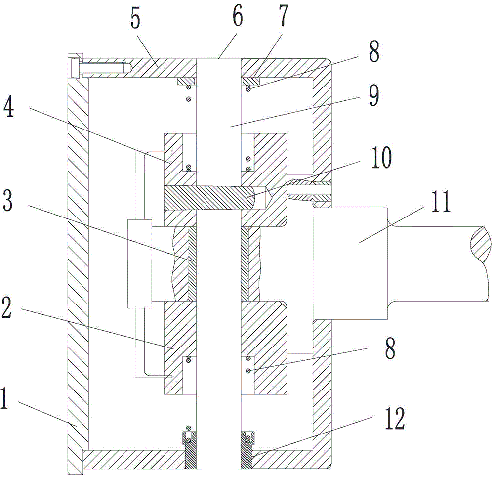
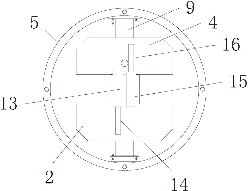
[0021] Such as figure 1 and figure 2 As shown, a vibration-proof centrifugal speed governor includes a housing 5, a sliding shaft 9 and a rotating shaft 11. The housing 5 is cylindrical in shape, and an end cover 1 is provided at its front end, and the sliding shaft 9 is arranged on the housing 5 and parallel to the bottom end of the housing 5, the side wall of the housing 5 is provided with a sliding shaft slide outlet 6, one end of the rotating shaft 11 extends into the housing 5 and is fixedly connected with the bottom end of the housing 5, The other end is located at the outer side of the housing 5 and is connected with the driving part. The rotating shaft 11 can drive the whole anti-vibration centrifugal speed governor to rotate. 1. The symmetrical setting of the s...


PUM


Abstract

The invention discloses a vibration prevention type centrifugal speed limiter which comprises a casing, a sliding shaft and a rotating shaft, wherein the sliding shaft is arranged in the casing and parallel to the bottom end of the casing; a sliding shaft sliding outlet is formed in the side wall of the casing, one end of the rotating shaft is fixedly connected with the bottom end of the casing, and the other end is located on the outer side of the casing and connected with a drive part; a static slider and a movable slider are symmetrically distributed on the sliding shaft, springs are arranged between the movable slider and the side wall of the casing as well as between the static slider and the side wall of the casing; the vibration prevention type centrifugal speed limiter further comprises a first damper and a second damper, the first damper is connected with the movable slider through a first pull rod, and the second damper is connected with the static slider through a second pull rod. The invention further provides a mining locomotive based on the vibration prevention type centrifugal speed limiter. The vibration prevention type centrifugal speed limiter is simple in structure and high in practicability, and reduces vibration influence on a brake process.

Description

technical field [0001] The invention belongs to the field of mining mechanical equipment, in particular to an anti-vibration centrifugal speed governor and a mining locomotive. Background technique [0002] At present, the domestic man-made vehicles used by mine inclined shafts to transport workers up and down, whether they are claw type or holding rail type, are equipped with broken rope braking and manual braking protection, but there is no overspeed braking protection device. When the winch is out of control or other reasons cause people and vehicles to run with ropes, neither of these two brake protections can effectively play their role, which brings great safety hazards to mine inclined shaft operators. Therefore, a reliable limit The speed device has become the guarantee for the safe operation of mining locomotives. The existing speed limiting devices are electronic and mechanical: the structure of the electronic speed limiter is complex, the dependence on external a...

Claims


Application Information

Patent Timeline
IPC IPC(8): F16D59/00B61H11/02
Inventor 齐辉朱高鹏刘青鞠彬王新超
Owner SHANDONG UNIV OF SCI & TECH
Why Eureka
Try Eureka